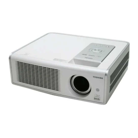
Toshiba TDP-MT700 Manual de servicio - Página 13
Navegue en línea o descargue pdf Manual de servicio para Proyector Toshiba TDP-MT700. Toshiba TDP-MT700 49 páginas. Home theater projector
También para Toshiba TDP-MT700: Manual del usuario (34 páginas), Manual del usuario (36 páginas)

MT700 Service Manual
4.1.1.3. Video port input circuit
1. Video decoder SAA7118:
The video decoder can accept 480i, 576i via component 1 and component 2 input
connectors. It also supports NTSC M, NTSC-J, PAL (included PAL M, PAL N), and
SECAM via S-Video connector and composite video connector.
This decoder will decode video inputs to ITU-R BT.656 digital format (DI_IN[2.9]).
The interlacing digital video outputs DI_INA[2..9] will go to de-interlace processor
FLI-2310.
2. De-interlace Processor FLI-2310:
The de-interlace processor accepts parallel digital ITU-R BT.656 data with H/V
sync. The output format is YCBCR 4:2:2 (V_IN[0..15]). This output is progressive
output with 31.5K Hsync and 27MHz pixel clock.
The SDRAM (2M x32) U11 is needed when FLI-2310 converts interlace video
input to progressive video output.
Comp 1 (480i, 576i)
Comp 2 (480i, 576i)
S-VIDEO
COMPOSITE VIDEO
4.1.1.4. Scalar and Micro-controller
1. CPU (RDC2021) 25Mhz
This CPU is used for controlling whole electronic boards and peripheral devices
(thermal control and IR receiving). For essential calculation and storage, it has
been set up with SRAM (128K x16), Flash ROM (256K x16) and EEPROM. The
SRAM is responsible for calculation. Flash is stored the system software.
YCBCR 4:2:2
(ITU-R BT.656 Format)
(8 Data Bits)
DI_INA[2..9]
DI_HSYNC, DI_VSYNC
VIDEO
DECODER
DI_27M_CLK
(SAA7118)
SDRAM control
address, data
(2M x 32)
Video Port Input Circuit
12
4:2:2 Format
(16 Data Bits)
V_IN[0..15]
V_HSYNC, V_VSYNC
DeInterlace
Processor
VCLK
FLI-2310
SDRAM
YCBCR
to Scalar
