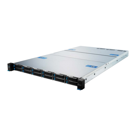
MSI S1205 Manual del usuario - Página 31
Navegue en línea o descargue pdf Manual del usuario para Servidor MSI S1205. MSI S1205 40 páginas.

5. Make sure the attached clips on the carrier grab onto the heatsink and firmly
secure the carrier, CPU and heatsink as one Processor Heatsink Module (PHM).
6. Remove the socket cover by squeezing the finger grips in, then flip 4 anti-tilt wires
on the heatsink to the unlocked position (inward) and place the PHM on top of the
bolster plate with the Pin 1 indicators aligned. Hold the PHM horizontally, carefully
lower down to engage PHM to bolster the plate's alignment pin.
7. Flip 4 anti-tilt wires to the locked position (outward) and make sure the latches of
the wires are firmly secure.
8. Tighten all screws on the PHM in diagonal sequences to secure the PHM to the
motherboard. (
Torque:
⚠
Important
∙
Whenever CPU is not installed, always protect your CPU socket pins with the plastic
cap covered.
∙
Do not touch the CPU socket pins to avoid damage.
∙
Read the CPU status in BIOS.
, 0.904 N·m = 9.2208 kgf·cm = 8 lbf·in
0.904 N·m
4 x anti-tilt wires
locked
)
CPU & Heatsink
31
