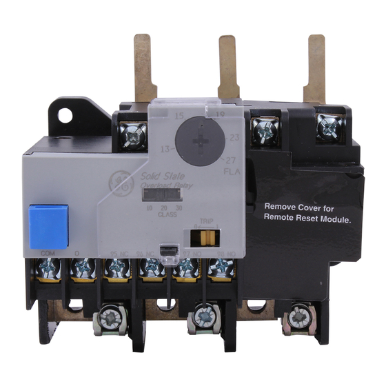
ABB CR324DXHP Manual del usuario - Página 4
Navegue en línea o descargue pdf Manual del usuario para Relés ABB CR324DXHP. ABB CR324DXHP 4 páginas. Solid state overload relay

2. Insert the power wires into the Panel Mount
Adapter screw clamps.
3. Tighten the power wire connections to 25 lb-in.
Use the following procedure to install a NEMA Size 2
Solid
State
Overload
CR324DX_) on a Panel Mount Adapter (catalog
number CR324DXPMA), as illustrated in Figure 8.
1. Align the slots in the base of the Solid State
Overload Relay with the keyed projections on the
Panel Mount Adapter baseplate, then slide the two
parts together until the Solid State Overload Relay
stabs engage the Panel Mount Adapter terminals.
2. Insert the three terminal mounting screws through
the Panel Mount Adapter, engaging the tapped
holes in the Solid State Overload Relay stabs.
3. Tighten the terminal mounting screws to 15 lb-in.
4. Insert the power wires into the bottom part o f the
lugs and tighten the lug screws to 16 lb-in.
Figure 7. Connecting a NEMA Size 1 Solid State Overload Relay and
Panel Mount Adapter.
NEMA Size2
Figure 8. Connecting a NEMA Size 2 Solid State Overload Relay and
Panel Mount Adapter.
These instructions do not cover all details or variations in equipment nor do they provide fo r every pos.si ble con tingency
that may be met in connection with installation, operation, or maintenance. Should further info rmation be desired or
should particular problems arise that are not covered sufficiently for the purchaser's purposes, the matter should be
referred to your local ABB Sales Office.
—
ABB Inc.
305 Gregson Drive
Cary, NC 27511.
electrification.us.abb.com
Relay
(catalog
number
Torque power
wire connections
to 25 lb-in
Torque terminal
mounting screw
to 151
—
We reserve the right to make technical
changes or modify the contents of this
document without prior notice. With
regard to purchase orders, the agreed
particulars shall prevail. ABB Inc. does not
accept any responsibility whatsoever for
potential errors or possible lack of
information in this document.
Figure 9 is a typical three-phase wiring diagram, while
Figure 10 is a typical single-phase wiring diagram
(drawing number 55-216176).
Wiring Diagrams
Figure 9. Typical three-phase wiring diagram.
Figure 10. Typical single-phase wiring diagram.
We reserve all rights in this document and
in the subject matter and illustrations
contained therein. Any reproduction or
utilization of its contents – in whole or in
parts – is forbidden without prior written
consent of ABB Inc.
Copyright© 2020 ABB
All rights reserved
L3
L1
L2
1--o
97 �
98
T3
L1
L2
1--o
97 �
98
T3
