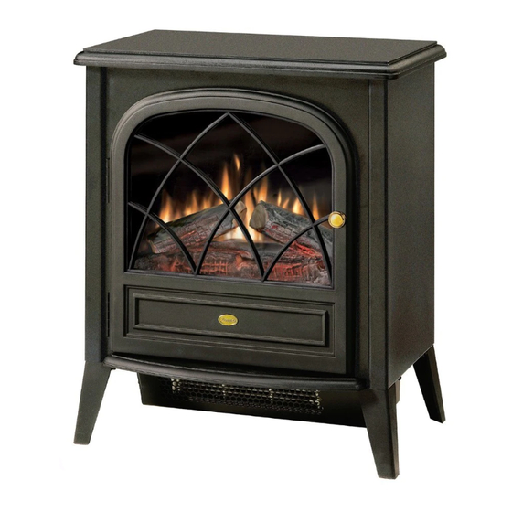
Dimplex CS33116A Manual de servicio - Página 10
Navegue en línea o descargue pdf Manual de servicio para Estufa Dimplex CS33116A. Dimplex CS33116A 13 páginas. Compact stove
También para Dimplex CS33116A: Manual del usuario (14 páginas)

that hold the Heater Assembly in place from the bottom
surface of the pan (Figure 13).
8. Remove the two (2) black metal stand off brackets from
the Heater Assembly by removing the two (2) Philips
screws that hold each bracket in place.
9. Remove the black metal baffle that surrounds the Heater
Assembly's Element by removing the four (4) Philips
Figure 14
Screws to remove (4)
screws that hold it in place. There are two (2) screws on
the top and bottom (Figure 14).
10. Attach the metal baffle and stand off brackets onto the
replacement Heater Assembly.
11. Reattach the Bottom Pan to the Heater Assembly using
the screws from step 7.
12. Attach the seven (7) wire clips removed in step 6 using
Figure 12 as a reference if needed.
13. Reattach Cutout to Heater Assembly using small Phillips
screw removed in step 5.
14. Reassemble the stove following steps 1 through 4 in
reverse order.
Thermostat Replacement
If the stove was operating prior to servicing allow at least
10 minutes for light bulbs and heating element to cool off to
avoid accidental burning of skin.
Disconnect power before attempting any maintenance or
cleaning to reduce the risk of electric shock or damage to
persons.
1. Open stove door.
2. Remove the 11 Philips screws that attach the top panel to
the stove as shown in Figure 4 (page 6). There are: four
(4) screws along each side; and three (3) screws at the
front, accessible behind the door.
3. Remove top panel.
4. Slide partially reflective glass up from within the stove to
remove.
5. Pull off the Thermostat knob from the rear of the stove.
6. Remove the two (2) silver Phillips screws that attach the
Figure 15
Blue wire clip leading to
lower section of stove
Thermostat to the back panel (Figure 15).
7. Remove the three (3) wire clips that attach to the
Thermostat, noting their original positions.
8. Orient replacement Thermostat and connect the wire
clips that were removed in step 7 (refer to Figure 15).
9. Attach Thermostat to inside surface of rear panel using
two (2) silver screws removed in step 6.
10. Follow steps 1 through 5 in reverse order to reassemble
stove.
Power Cord Replacement
If the stove was operating prior to servicing allow at least
10 minutes for light bulbs and heating element to cool off to
avoid accidental burning of skin.
Disconnect power before attempting any maintenance or
cleaning to reduce the risk of electric shock or damage to
persons.
Replacement Procedure:
1. Open stove door.
2. Remove the 11 Philips screws that attach the top panel to
the stove as shown in Figure 4 (page 6). There are: four
(4) screws along each side; and three (3) screws at the
front, accessible behind the door.
3. Remove top panel.
4. Slide partially reflective glass up from within the stove to
remove.
5. On the back panel of the stove, remove the two (2)
Phillips screws that hold the Power Cord Access Panel in
place (Figure 16, page 11).
6. Pull the Access Panel off of the Power Cord (Figure 17).
7. Cut any zip ties that may hold the Power Cord in place
within the stove and trace the power cord wires to where
they connect.
The ribbed edge of the power cord connects to the far
10
Thermostat
Paired wire clips - 1 to Remote
Control receiver, 1 to lower sec-
tion of stove
