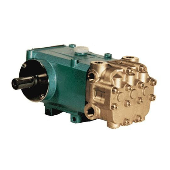
ARIMITSU 511 Información sobre instalación y puesta en marcha - Página 4
Navegue en línea o descargue pdf Información sobre instalación y puesta en marcha para Bomba de agua ARIMITSU 511. ARIMITSU 511 6 páginas.

INLET PRESSURE should fall within the specifications of the pump.
o Optimum pump performance is obtained with +15 PSI (1 BAR) inlet pressure.
o With adequate inlet plumbing, most pumps will perform with flooded suction.
Maximum inlet pressure is 75 PSI (5 BAR).
o After prolonged storage, pump should be rotated by hand and purged of air to
facilitate priming.
o Disconnect the discharge port and allow liquid to pass through pump and
measure flow.
INLET ACCESSORIES are offered to protect against over pressurization,
contamination or temperature and control flow.
o A shut-off valve is recommended to facilitate maintenance.
o Inspect and clean inlet filters on a regular schedule to avoid flow restriction.
o All accessories should be sized to avoid restricting the inlet flow.
o All accessories should be compatible with the solution being pumped to
prevent premature failure or malfunction.
o A gauge between filter and pump will indicate pump inlet pressure. Avoid
negative pressure (vacuum) inlet conditions.
BY-PASS TO INLET Care should be exercised when deciding the method of by-pass
from control valves.
o It is recommended the bypass be directed to a baffled reservoir tank, as
described above.
o Although not recommended, bypass liquid may be returned to the inlet line of
the pump. With a pressurized inlet system only, a thermo relief valve should be
used in the by-pass line to monitor the temperature build-up in the by-pass
loop to avoid premature seal failure.
o A reinforced flexible, low-pressure hose rated up to 300 PSI should be used for
bypass flow back to inlet.
o Caution should be exercised not to under size the bypass hose diameter
and length.
o Check the pressure in the bypass line to avoid over pressurizing the inlet.
o The by-pass should be connected to the pump inlet line with a constant
downward slope.
PREVENTATIVE MAINTENANCE CHECK-LIST
Check
Daily
Weekly
Clean Filters
X
Oil Level/Quality
X
Oil Leaks
X
Water Leaks
X
Belts/Pulley
Plumbing
Initial Oil Change
Oil Change
Seal Change
Valve Change
Accessories
* If other than Arimitsu oil is used, change cycle would be every 300 hours
** Each system's maintenance cycle will be exclusive. If system performance
decreases, check immediately. If no wear at 1500 hours, check again at 2000
hours and each 500 until wear is observed. Valves typically require changing
every other seal change. Duty cycle, temperature, quality of pumped liquid
and inlet feed conditions all effect the life of pump wear part and
service cycle.
** Remember to service the regulator/unloader at each seal servicing and check
all system accessories and connections before resuming operation.
INLET CONDITION CHECK-LIST
MAINTENANCE AND SERVICE TIPS
50 hrs.
500 hrs.*
1500 hrs.** 3000 hrs.**
X
X
X
X
X
X
INLET SUPPLY should exceed the maximum flow being delivered by the pump to
assure proper performance.
o Open inlet shut-off valve and turn on water supply to avoid starving pump.
DO NOT RUN PUMP DRY.
o Temperatures above 120°F are permissible. Add 1 PSI inlet pressure per each
degree F over 120°F. Seal material or RPM changes may be required.
o Avoid closed loop systems especially with high temperature fluid or large
flows. The type of unloader or regulator can vary the effects of closed
loop bypass.
o Higher viscosity, thicker liquids require a positive head (0+ PSI) and RPM
changes may be required. Horsepower requirements may increase.
o When using a supply tank, size it to provide an adequate supply of water and
enough volume to decrease turbulence created from bypass return stream.
Generally, a minimum of 5 times the GPM although several system factors can
affect this. Provide adequate baffling in the tank to eliminate air bubbles and
turbulence; install diffusers on all return lines to the tank. Do not locate supply
ports next to bypass return ports.
o Supply tanks should be located above pump inlet with inlet lines plumbed from
the bottom of the tank.
o Tank fed, suction systems should have a constant downward slope into
pump inlet.
o Make sure adequate filtration exists to prevent debris from damaging pump.
INLET SIZE should be adequate to avoid starving the pump.
o Line size must be a minimum of one common size larger than the pump inlet
fitting. Avoid tees, 90-degree elbows or valves in the inlet line of the pump to
reduce the risk of flow restriction and cavitation.
o The line must be a FLEXIBLE reinforced hose, NOT a rigid pipe. Soft hose can
decrease system vibration.
o All systems should use a minimum of fittings and turns.
o Use an approved pipe sealant or tape to assure airtight, positive sealing of
all connections.
SERVICE INTERVALS:
• Change Oil (PN30103) every 500 hours.
• Change high-pressure and low-pressure seals every 1500 hours.
• Change valves every 3000 hours.
SERVICE TIPS:
• When pumping harsh chemicals, flush out chemical residue
immediately after use. Do not leave chemicals inside pump.
If it is not water or anti-freeze, flush from pump before storage.
• If the pump is used in areas or times of freezing, pump it dry
or leave anti-freeze in at time of storage.
• Use case and maintenance to prolong the life of the equipment.
X
