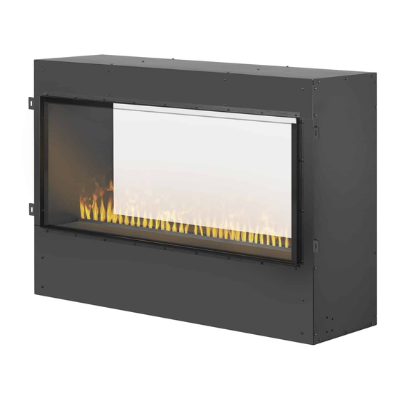
Dimplex CDFI-BX1000 Manual de servicio - Página 7
Navegue en línea o descargue pdf Manual de servicio para Calentador eléctrico Dimplex CDFI-BX1000. Dimplex CDFI-BX1000 8 páginas.
También para Dimplex CDFI-BX1000: Instrucciones de montaje (3 páginas), Instrucciones de montaje (3 páginas)

Heater Assembly Replacement
WARNING: Disconnect power before attempting
any maintenance or cleaning to reduce the risk of
electric shock or damage to persons.
CAUTION: If unit was operating prior to servicing
allow at least 10 minutes for lights and heating
elements to cool off to avoid accidental burning of
skin.
Tools required: Phillips head screwdriver
Side cutters
! NOTE: While not necessary, it may be helpful
to have a second person to assist in holding
the upper components while the other person
completes the service on the heater assembly.
1. Remove the front glass by pulling it up and out.
Ensure that it is kept in a safe place during the
service.
2. Remove the hole plugs that conceal the holes on
the front of the heater exhaust bracket.
3. Remove the heat exhaust bracket at the top of
the pro-box by unscrewing the screws in the front
which are accessed through the holes, as well
as the screws in the back (CDFI-BX1000 has 8
screws in total, and the CDFI-BX1500 has 12
screws in total). (Figure 3)
Figure 3
Figure 4
Heater
Cover Plate
Heater Assembly
Retaining Brackets
Retaining Bracket
Screws
4. Remove the heater cover plate by unscrewing the
12 screws around its periphery. Be sure to hold
the heater assembly as it comes down.
5. Remove the 4 screws that secure the retaining
brackets to the heater cover plate. (Figure 4)
6. Remove the 2 screws on each retaining bracket
(4 total) that secure each bracket to the heater
assembly. Set the brackets aside. (Figure 5)
7. Snip the two cable ties that secure the wires to the
heater assembly.
8. Disconnect the wires from the heater assembly,
noting their original locations. It can be helpful to
take a picture of the heater assembly connections
before the wires are disconnected in order to keep
track of each wire's place.
9. Secure each of the two retaining brackets to the
new heater assembly.
10. Reconnect the wires to the new heater assembly.
Use the provided cable ties to secure the wires
to the heater assembly, ensuring that they do not
interfere with the fan or the element.
11. Secure the retaining brackets to the heater cover.
12. Reassemble the unit in the reverse order as
above.
Heater Exhaust Bracket
Figure 5
7
