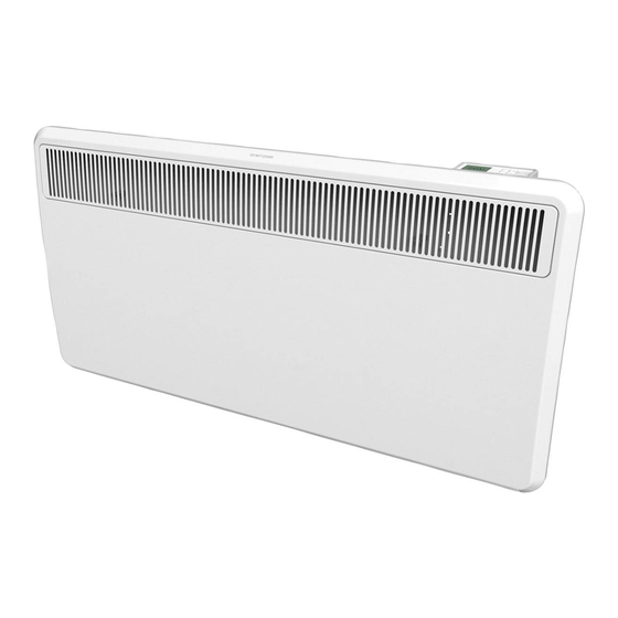
Dimplex PLX 750 Manual de instrucciones de instalación y funcionamiento - Página 9
Navegue en línea o descargue pdf Manual de instrucciones de instalación y funcionamiento para Calentador eléctrico Dimplex PLX 750. Dimplex PLX 750 16 páginas. Plx panel convector heaters
También para Dimplex PLX 750: Instrucciones de instalación y funcionamiento (4 páginas), Instrucciones de instalación y funcionamiento (5 páginas), Instrucciones de instalación y funcionamiento (4 páginas)

2. Technical Description
150
3. Mounting, Installation, Minimum Clearances
The heater must be installed in a horizontal position on
a vertical wall as shown in the illustration.It is permissi-
ble to mount the heater to a wooden wall.
Ensure that air can enter and leave the heater freely, at
the inlets below and the outlets above
The electrical connection box must be accessible after
the heater has been mounted. Be careful of flammable
objects!
It is absolutely necessary that the minimum clearances
indicated in the mounting diagram be maintained. Be-
yond that, a clearance space of at least 500 mm is to
be provided in front of the appliance.
The mains socket must be accessible after the appliance has
been mounted.
3.1 Wall Mounting
IMPORTANT- The original wall mounting bracket sup-
plied, located at the back of the heater, must be used.
Remove the bracket from the
back of the device by pressing
the springs on each side.
Drill the fixing holes for the wall
mounting bracket.
Firmly secure bracket to the wall
using suitable screws.
Insert heater in wall bracket making use of the slots
on the back of the heater.
Snap heater in place at the top of the wall bracket.
www.dimplex.de/en
PLX 500, PLX 750, PLX 1000, PLX 1500, PLX 2000TI, PLX 2500, PLX 3000
150
430
150
.
4. Electrical Connection
It is imperative that all current standards and relevant
installation provisions be adhered to.
The heater models PLX 2500 and PLX 3000 are fitted
with a supply cord without a plug. The supply cord must
be connected to a suitable connection box.
The hardwired electrical installation must be provided
with a disconnect device with a contact gap of at least
3 mm at each pole (e.g. automatic circuit breaker).
NDPGEP5RG · 07/14/B
Drilling dimensions in mm (front view)
150
118
A
255
Type
Rated Power
PLX 500
500 W
PLX 750
750 W
PLX 1000
1000W
PLX 1500
1500W
PLX 2000TI
2000W
PLX 2500
2500 W
PLX 3000
3000 W
214
150
141
430
184
105
150
65
A (mm)
116
286
286
354
526
526
526
EN-9
