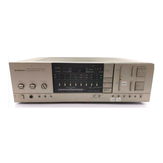
Pioneer SX-6 Manual de servicio - Página 5
Navegue en línea o descargue pdf Manual de servicio para Receptor Pioneer SX-6. Pioneer SX-6 25 páginas. Computer controlled stereo receiver
También para Pioneer SX-6: Manual de servicio (15 páginas)

@) PRESET-VOLUME
SWITCH
This is depressed when the volume
level is to be set to
the preset
level
(the PRESET
STEP
indicator
lights).
When presetting the volume level, depress the MEMORY/
STOP switch with the volume level still indicated on the
display, and then depress the PRESET-VOLUME
switch.
@) STATION CALL SWITCHES
These are pressed to call out preset broadcasting stations
and to preset the station.
To call out a station, first set the desired frequency band
using the FM or AM switches and then press the desired
switch.
@) INPUT INDICATORS
These light when the INPUT
(PHONO or AUX/VIDEO)
switch is pressed.
@) AUTO/MANUAL SELECTOR
This is used to select the reception mode.
AUTO
(released
position):
Auto
tuning
is selected
in
accordance with the position selected by the STATION
SCAN/STATION SEARCH selector on the right.
MANUAL
(depressed position): For manual tuning
Depress the TUNING
switch and tune in the station.
manually. Each time the TUNING
switch is depressed,
the frequency
changes
in 100kHz
steps during
FM
reception
and
in 9kHz
or
10kHz
steps during AM
reception in accordance with the position of the AM
CHANNEL
STEP switch. When the TUNING switch is
kept depressed, the frequency is continuously scanned.
Tuning
stops when
the upper
or lower
limit of the
frequency band is reached.
STATION SCAN/STATION SEARCH
SELECTOR
This is used
to select the auto
tuning mode
when
the
AUTO/MANUAL
selector switch on the left is at AUTO.
STATION SCAN: When the TUNING switch is depressed,
the broadcasting stations start to be scanned and this
procedure
stops once
a station has been picked up.
The
program
of that station
is heard
for about
5
seconds. The tuning operation then resumes and sound
is heard in the same way. Each of the stations is thus
picked up in turn.
When
the MEMORY/STOP
switch
is depressed once
you hear the sound of the desired program, the tuning
Operation
stops
and
the unit
is set to the reception
mode.
STATION
SEARCH:
When
the TUNING
switch
is de-
pressed, the broadcasting stations start to be scanned,
but this operation stops once a station has been picked
up and the unit is set to the reception mode. Depress
the TUNING
switch if the station picked up is not the
one
desired.
The
tuning
operation
now
starts over
again.
@ TAPE MONITOR INDICATOR
This lights when the TAPE (1 or 2/ADPT) switches are de-
pressed.
MEMORY/STOP SWITCH
This switch is used to preset the broadcasting stations into
the STATION
CALL
switches
or to preset the desired
volume level into the PRESET-VOLUME
switch.
This
switch
is also used to stop the tuning operation
during
the
STATION
SEARCH
or
STATION
SCAN
functions.
@) TAPE SWITCHES
1:
Depress this switch to monitor the recording or
playback of a tape on the tape deck connected
to the TAPE 1 jacks (REC and PLAY).
2/ADPT:
This is depressed
when
using a tape deck or
adaptor unit connected to the rear panel TAPE
2/ADAPTOR jacks.
NOTE:
Depress switch
1 and release switch 2/ADPT
when
dubbing a
tape in the deck connected to the TAPE 7 jacks onto a tape in
the deck connected to the TAPE 2/ADAPTOR jacks.
62 MONO MUTE OFF SWITCH
The sound is heard in mono when this switch is set to the
depressed
position. Normally,
the switch is kept at the
released position. During FM or AM reception, the noise is
reduced and reception is made clear. When the station is
distant
and its signals are weak, depress the switch
and
tune in the station manually.
63 SUBSONIC SWITCH
The subsonic
filter with
the 15Hz cut-off frequency is
actuated when
this switch is depressed. This filter serves
to attenuate
the
frequencies
lower
than
15Hz
with
a
6dB/oct. slope and, therefore, it can be used to suppress
the ultra-low-range
noise which
is generated
by record
warp
and other factors. This noise cannot
actually
be
heard by the ear but it can cause cross modulation distor-
tion
and
even
speaker
damage.
Use
this switch
when
required during record play.
@4 LOUDNESS SWITCH
When listening to a performance with the VOLUME
level
is low, depress this switch and the bass and treble will be
accentuated.
When the volume is low, the human ear finds it harder to
hear the bass and treble than when the volume is high.
The LOUDNESS
switch is thus designed to compensate
for this deficiency.
3. BLOCK
DIAGRAM
FM TUNER
MIX!
1F AMP
RF AMP
a
FM ANTENNA
soon
|
=
: La —#
Hy
ENE Fe]
ieee
Q
8 ae
BUFFER
uf
Ry
I
| AM
TUNER
AM_TUNER
AM
ANTENNA
ae
IF AMP, DETECTOR
MPX
DECODER
LLRF.
AF AMP
2
12
43
g
1 IN
OUT 6
{PA3001-A)
21IN
LOUT4
L OUT
(TO FUNCTION)
R OUT
i
(TO FUNCTION)
3
(HAIIS6W-P)
W
ROUT
5
PRESCALAR
& PLL
CIRCUIT
4
3 1FM
7
im
XS
CS
|
| py
LI
| |
Fei
DISPLAY
DISPLAY
Ia
CIRCUIT
INVERTER
I
oe
aioe
3
GSD
{TC40498P)
> Kw
ec,
[>°
[| *
DISPLAY
DRIVE
1
e}
Cy
o
(T6301
>
3
3
P)
es I |
+87
Wy
+87
SOT"
es
mh
ot
ld
ae
ag
i
a:
lt)
SOOkH:
BE
i
FROM
AM
TUNER
FROM
FM
TUNER
2
MUTING
IND.
TOR CH
EQUALIZER
AMP
35.6
dB( AT tkHz)
(NJM4558DXC)
| TAPE 1 ADAPTOR
!
vice ©
FUNCTION
ee
. Py
(PA4008)
REC
PLAY
OUT/
IN/
TORCH
REC
PLAY
"API
TARE
ADAPTOR /TAPE 2
—+35V(+BS)
+ 42.5V(+B1)
+28V(+B2)
+418.6
Vi +B3)
VOLUME
& MU
(PASO04)
+ BALANCE
TING
+12.2V(+B6)
+ 4.9V (+ B7)
+4.9V (+88)
OVERLOAD
DETECTOR
TONE
CONTROL
SPEAKERS
~——~B
