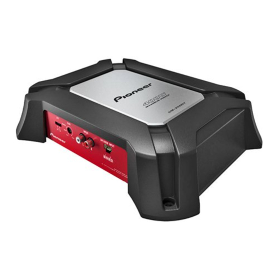
Pioneer GM-3500T/XZUC Manual de servicio - Página 6
Navegue en línea o descargue pdf Manual de servicio para Amplificador Pioneer GM-3500T/XZUC. Pioneer GM-3500T/XZUC 28 páginas. Bridgeable two-channel power amplifier
1
2. SPECIFICATIONS
2.1 SPECIFICATIONS
A
• GM-3500T/XZUC
Power source............................14.4 V DC (10.8 V to 15.1 V
Grounding system.................. Negative type
Current consumption ............15 A (at continuous power,
Average current drawn.........4 A (4 Ω for two channels)
Backup current ....................... 1 mA or less
Fuse................................................ 2 5 A × 1
Dimensions (W × H × D) ... 289 mm × 62 mm ×
B
Weight ........................................ 2.0 kg (4.4 lbs)
Maximum power output .......400 W (200 W × 2)
Continuous power output ... 60 W × 2 (at 14.4 V, 4 Ω,
Load impedance ..................... 4 Ω (2 Ω to 8 Ω allowable)
C
Frequency response...............10 Hz to 70 kHz (+0 dB,–
Signal-to-noise ratio.............. 98 dB (IHF-A network)
Distortion ................................... 0.05 % (10 W, 1 kHz)
Low pass filter:
Cut off frequency .......... 80 Hz
Cut off slope .................... –12 dB/oct
Gain control:
RCA .................................... 200 mV to 6.5 V
Speaker ............................ 0.8 V to 26 V
Maximum input level / impedance:
RCA .................................... 6.5 V / 22 kΩ
Speaker ............................ 26 V / 22 kΩ
CEA2006 Specifications
D
Power output ........................... 60 W RMS × 2 Channels (at
S/N ratio ..................................... 80 dBA (reference: 1 W into
Notes
E
Specifications and the design are subject to
modifications without notice.
The average current drawn is nearly the maxi-
mum current drawn by this unit when an
audio signal is input. Use this value when
working out total current drawn by multiple
power amplifiers.
F
6
1
2
allowable)
4 Ω)
7 A (4 Ω for one channel)
219 mm
(11-3/8 in. × 2-1/2 in. ×
8-5/8 in.)
(Leads for wiring not in-
cluded)
< =
20 Hz to 20 kHz,
1.0 % THD
+N)
185 W × 1 (at 14.4 V, 4 Ω
< =
BRIDGE 1 kHz,
1.0 % THD
+N)
85 W × 2 (at 14.4 V, 2 Ω,
< =
1 kHz,
1.0 % THD+N)
3 dB)
14.4 V, 4 Ω and
< =
1 % THD
+N)
4 Ω)
GM-3500T/XZUC
2
3
• GM-3500T/XZEW5, XZES
Power source............................14.4 V DC (10.8 V to 15.1 V
allowable)
Grounding system.................. Negative type
Current consumption ............15 A (at continuous power,
4 Ω)
Average current drawn........ 4 A (4 Ω for two channels)
7 A (4 Ω for one channel)
Backup current ....................... 1 mA or less
Fuse.............................................. 25 A × 1
Dimensions (W × H × D) ... 289 mm × 62 mm × 219
mm
Weight ........................................ 2.0 kg (Leads for wiring not
included)
Maximum power output .......400 W (200 W × 2)
Continuous power output ... 60 W × 2 (at 14.4 V, 4 Ω,
20 Hz to 20 kHz,
+N)
185 W × 1 (at 14.4 V, 4 Ω
BRIDGE 1 kHz,
+N)
85 W × 2 (at 14.4 V, 2 Ω,
< =
1 kHz,
Load impedance ..................... 4 Ω (2 Ω to 8 Ω allowable)
Frequency response...............10 Hz to 70 kHz (+0 dB,–
3 dB)
Signal-to-noise ratio.............. 98 dB (IEC-A network)
Distortion ................................... 0.05 % (10 W, 1 kHz)
Low pass filter:
Cut off frequency .......... 80 Hz
Cut off slope .................... –12 dB/oct
Gain control:
RCA .................................... 200 mV to 6.5 V
Speaker ............................ 0.8 V to 26 V
Maximum input level / impedance:
RCA .................................... 6.5 V / 22 kΩ
Speaker ............................ 26 V / 22 kΩ
Notes
Specifications and the design are subject to
modifications without notice.
The average current drawn is nearly the maxi-
mum current drawn by this unit when an
audio signal is input. Use this value when
working out total current drawn by multiple
power amplifiers.
3
4
< =
1.0 % THD
< =
1.0 % THD
1.0 % THD+N)
4