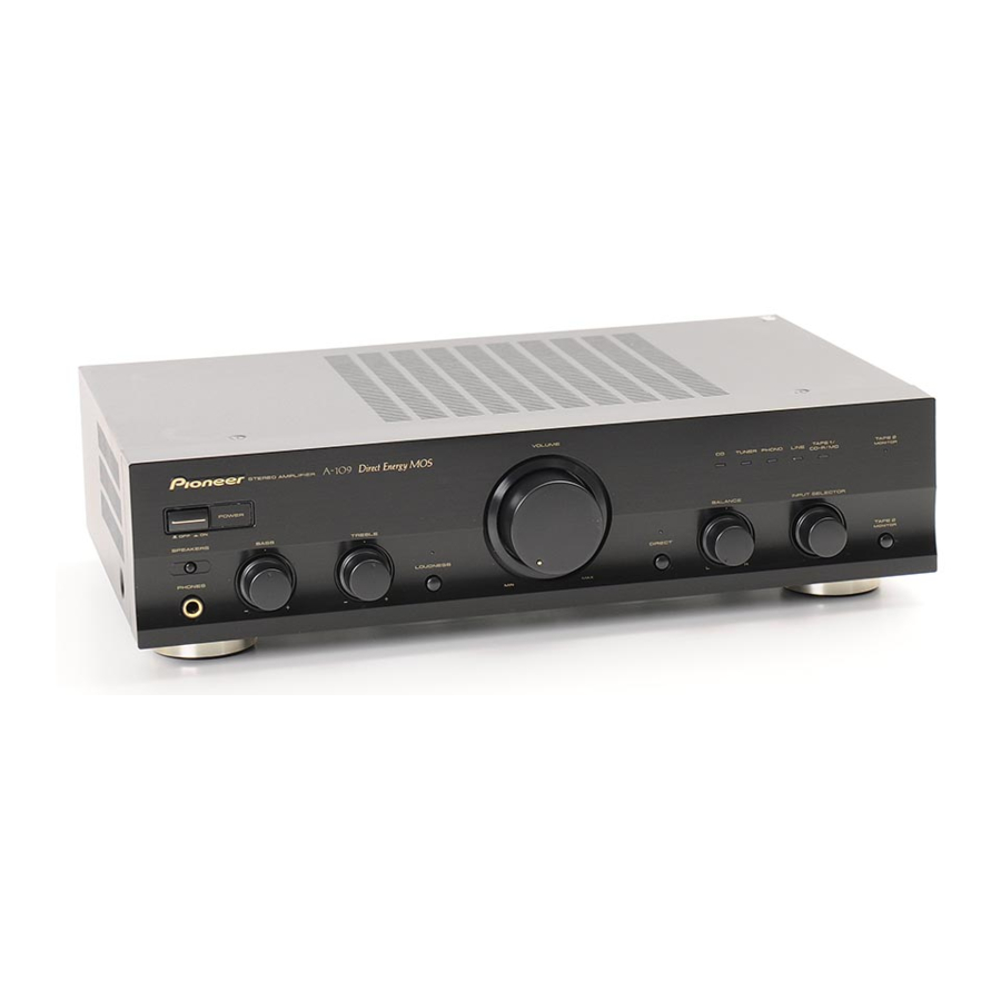
Pioneer MYXJ Manual de servicio - Página 2
Navegue en línea o descargue pdf Manual de servicio para Amplificador Pioneer MYXJ. Pioneer MYXJ 6 páginas. Stereo amplifier

1
1. CONTRAST OF MISCELLANEOUS PARTS
NOTES:
Parts marked by "NSP" are generally unavailable because they are not in our Master Spare Parts List.
The
mark found on some component parts indicates the importance of the safety factor of the part.
A
Therefore, when replacing, be sure to use parts of identical designation.
Screws adjacent to
Reference Nos. indicate the pages and Nos. in the service manual for the base model.
j
For the applying amount of lubricants or glue, follow the instructions in this manual.
(In the case of no amount instructions, apply as you think it appropriate.)
•
When ordering resistors, first convert resistance values into code form as shown in the following examples.
Ex.1 When there are 2 effective digits (any digit apart from 0), such as 560 ohm and 47k ohm (tolerance is shown by J=5%,
and K=10%).
560 Ω
47k Ω
0.5 Ω
1 Ω
Ex.2 When there are 3 effective digits (such as in high precision metal film resistors).
B
5.62k Ω
CONTRAST TABLE
A-109/MYXJ7 and A-209R/MYXJ are constructed the same except for the following :
Ref.
Mark
No.
PCB ASSEMBLIES
NSP
CONTROL ASSY
P5- 1
P5- 2
P5- 3
C
NSP
AF COMPLEX ASSY
P5- 6
P5- 7
PACKING SECTION
P3- 1
Operating Instructions (English)
P3- 2
Operating Instructions (German)
P3- 3
Operating Instructions (French/Italian/
P3- 4
NSP
Warranty Card
P3- 5
Remote Control Unit (CU-A019)
P3- 6
Battery Cover
D
P3- 7
NSP
Dry Cell Battery (R6P/AA)
P3-11
Packing Case
Label (WEEE)
IEC65-7 Caution
EXTERIOR SECTION
P5- 8
Fuse (FU1 : 1.25A)
P5- 8
Fuse (FU1 : 800mA)
P5-11
Power Transformer (AC 220 V to 230 V)
P5-12
NSP
Chassis
P5-13
Rear Panel
E
P5-18
Nut
P5-25
NSP
Shield Plate
P5-26
Screw (3x8)
P5-28
IR Filter
P5-36
Bonnet Case
P5-38
Front Panel
P5-39
Screw
P5-41
Nut
P5-44
PVC Cover
P5-45
Foot
P5-47
Transformer Plate
P5-48
NSP
Sub Frame
F
∗
1 : Refer to " 7 CONTRAST OF PCB ASSEMBLIES " and " 2. SCHEMATIC DIAGRAM ".
∗
2 : Refer to A-209/SBDXJ on the service manual RRV2283.
2
1
2
mark on product are used for disassembly.
p
→
56 × 10
→
1
→
47 × 10
→
3
→
R50 ..................................................................................... RN2H
→
1R0 ..................................................................................... RS1P
→
562 × 10
→
1
Symbol and Description
FRONT L ASSY
FRONT R ASSY
OPT ASSY
VOLUME ASSY
AF ASSY
Dutch/Swedish/Spanish/Portuguese)
2
3
f
y
561 ........................................................ RD1/4PU
473 ........................................................ RD1/4PU
5621 ...................................................... RN1/4PC
A-209R
/MYXJ
AWG7013
AWX7123
AWX7124
AWX7125
AWM7357
AWX7118
AWX7117
ARB7236
ARC7322
ARC7323
ARY7022
AXD7193
AZN2249
VEM-013
AHD7869
Not used
Not used
REK1023
Not used
ATS7190
ANA7064
ANC7925
ABN-065
ANK7043
PBA1096
AAK8076
ANE7183
AMB7710
BBZ30P080FZK
NK90FUC
Not used
Not used
ANG7312
ANG7313
A-109
3
4
J
5 6 1
J
4 7 3
K
R 5 0
K
1 R 0
F
5 6 2 1
Part No.
A-109
/MYXJ7
AWG7011
AWX7120
AWX7121
Not used
AWM7969
AWX7112
AWX8601
ARB7237
ARC7324
ARC7325
ARY7065
Not used
Not used
Not used
AHD7872
ARW7322
ARM7106
Not used
REK1021
ATS7417
ANA7177
ANC7931
ABN7002
Not used
ABA7127
Not used
ANE7338
AMB7712
BBZ30P080FTB
NK90FTC
AAK7541
REC1263
ANG7535
ANG7536
4
Remarks
∗1
∗2
∗2
∗1
