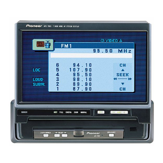
Pioneer AVX-7000 Manual de servicio - Página 15
Navegue en línea o descargue pdf Manual de servicio para Monitor Pioneer AVX-7000. Pioneer AVX-7000 16 páginas. 7 inch wide av system display
También para Pioneer AVX-7000: Manual (24 páginas), Manual de servicio (32 páginas)

3No power
No power
NO
F801 (fuse) is broken out?
YES
18.5V is obtained at TP02? If not, the resistance
between TP02 and GND is 100k ohms or more?
7V is obtained at TP03? if not, the resistance
between TP03 and GND is 500 ohms or more?
5V is obtained at TP04? If not, the resistance
between TP04 and GND is 35 ohms or more?
(-15.5)V is obtained at TP05? If not, the resistance
between TP05 and GND is 950 ohms or more?
(-5)V is obtained at TP06? If not, the resistance
between TP06 and GND is 400 ohms or more?
Input voltage 9V is obtained at
Pin-5 of Q801 (FA7610N)?
Triangular waves are obtained at
Pin-6 of Q801 (FA7610N)?
Switching waves are obtained at Q804 (TR)?
Check Transformer (T801) and replace it.
4Out of Sync
Out of Sync
YES
Video signal is obtained at Q653 (TR)?
Video signal is obtained at Pin-60
of Q201 (NJW1300A)?
Full-wave oscillating waveform is obtained at
Pin-55 and Pin-56 of Q201 (NJW1300A)?
5V is obtained at Pin-61 of
Q201 (NJW1300A)?
NO
Replace F801.
NO
Check 18.5V line to remove short-cir-
cuits. (CN003 and its periphery)
Check 7V line to remove short-circuits.
(Q201, Q202, Q203, and their periphery)
Check F801, input flexible cables, and their periphery.
Check Q801 and its periphery.
Check Q801 and its periphery.
NO
Check input flexible cables, Q651, and their periphery.
Check R229 (LPF, 360 ohms) and its periphery.
Go to item3 No power.
AVX-P7000CD,AVX-7000
Check 5V line to remove short-circuits.
(Q201, Q208, Q651, and their periphery)
Check (-15.5)V line to remove short-circuits.
(Q881, CN003, and their periphery)
Check (-5)V line to remove short-circuits.
(Q201, Q202, Q203, and their periphery)
Check X202 (Ceramic resonator) and its periphery.
15
