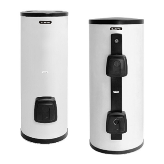
Ariston 506457 Manual - Página 15
Navegue en línea o descargue pdf Manual para Calentador de agua Ariston 506457. Ariston 506457 25 páginas.

- small-size tubes
- taps with ceramic plates,
it is necessary to install pressure stabilisers, ram stabilisers or an expansion vessel that is
suited to the installation as close as possible to the taps.
The working life of the water heater is affected by the operation of the galvanic anti-corrosion
system, therefore it cannot be used when the water hardness is permanently below 12° F.
However, in the presence of particularly hard waters, there will be a considerable and rapid
formation of limescale inside the appliance, with a consequent loss in efficiency and damage
to the electric heating element.
Electrical connection
Before performing any operations, disconnect the appliance from the electricity mains using
the external switch.
For greater safety, have qualified personnel carry out a careful inspection of the electrical
system, ensuring it complies with the applicable norms in force, because the appliance
manufacturer will not be held responsible for any damage caused by the lack of ear thing of
the system or for faults in the supply of electricity.
See warning no. 24
! ! ! ! !
Check that the system is suitable for the maximum power absorbed by the water heater (please
refer to the data plate) and that the cross-section of the electrical connection cables is suitable,
2
and no less than 1.5 mm
.
The appliance comes with a power supply cable; should it need to be replaced, you must use a
cable with the same characteristics (model HO5W-F 3x1,5 mm
see figure 8,9,10 concerning the electrical connection diagrams). The power supply cable should
be threaded along the special passage recessed into the rear of the appliance until it reaches the
thermostat housing (fig. 8). The connection should be made directly on the thermostat terminals
(M fig.5) for the single-phase models (respect the L-N polarity), or to the terminal board for the
three-phase models (see Area X in figure 8,9 and 10).
To disconnect the appliance from the mains, use a bipolar switch in compliance with the applicable
regulations in force (contact opening min. 3 mm, even better if fitted with a fuse).
The appliance must be ear thed and the earth wire (yellow-green in colour and longer than the
others) must be connected to the terminal marked with the symbol
power supply cable on the cap using the special cable clamp provided with the appliance.
See warning no. 11
! ! ! ! !
The use of multiplugs, extensions or adaptors is strictly prohibited.
It is strictly forbidden to use the piping from the hydraulic, heating and gas systems for the
appliance ear thing connection.
The appliance is not protected against the effects caused by lightning.
Before turning the appliance on, make sure the supply voltage complies with the value stated on
the appliance data plate and that the appliance itself is filled with water.
Starting and testing the appliance
Before powering the appliance, fill the tank up with mains water.
2
2
, 4x1,5 mm
and 4x2,5 mm
(G fig.5). Secure the
27
The filling is carried out by opening the domestic system central tap and hot water tap, until the
air is completely released.
Visually check for water leaks from the flange and slightly tighten it, if necessary.
Energise the system from the external switch
Adjusting the operating temperature
For the models that do not have external adjustment, the thermostat is adjusted in its maximum
position; if you want to decrease the temperature to reduce consumption, you must disconnect
the appliance from the electricity mains, remove the cap and delicately turn the thermostat
knob, where the adjusting references are indicated with + and – signs, clockwise using a
screwdriver (V fig.7).
Remount everything in the reverse order, paying par ticular attention to repositioning the
components correctly.
THERMOELECTRIC MODELS
All the instructions in this manual also refer to the thermoelectric models. An additional operation for
these appliances is the connection to the piping of the appropriate heating system.
Connect the top joint of the water heater to the rising column of the heating system and the bottom one
to the descending column, placing two taps in between.
The bottom tap, which is more accessible, is used to exclude the appliance when the heating system is
not operating.
2
;
The temperature of the water inside the coil must not exceed 95°C.
A device to expel the air from the exchanger's system must be fitted.
MAINTENANCE REGULATIONS (for authorised staff)
ATTENZIONE! Seguire scrupolosamente le avvertenze generali e le norme
! ! ! ! !
di sicurezza elencate all'inizio del testo, attenendosi obbligatoriamente a
quanto indicato.
All maintenance operations and interventions should be performed by qualified staff (who
have the skills required by the applicable norms in force).
Before carrying out any maintenance and/or replacement of components, disconnect the appli-
ance from the electricity mains using the external switch; if necessary, empty the water heater
by closing the main tap and letting the water out from the inside by means of an inlet tube after
having opened the discharge B and a hot-water tap (see fig. 2A-2B).
! ! ! ! !
See warning nos. 20, 26, 28
Replacing parts, when necessary
Remove the cap to have access to the electrical components.
28
