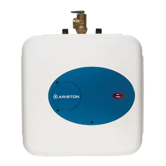
Ariston GL 6+ Manual de instrucciones - Página 8
Navegue en línea o descargue pdf Manual de instrucciones para Calentador de agua Ariston GL 6+. Ariston GL 6+ 37 páginas. Electric mini tank water heaters
También para Ariston GL 6+: Manual del usuario (12 páginas), Manual de instalación (14 páginas), Manual del usuario (12 páginas), Manual del usuario (14 páginas), Sustitución del termostato (3 páginas)

Maintenance instructions
Note: Do not attempt to repair this water heater yourself. Call a service person
Periodic maintenance
Removing
Note: For most of these operations, the water will have to be drained from the heater.
the cover
Draining
1) If the heater has been installed with flexible hoses, shut off the power supply and
turn the heater upside down over a sink to drain the water out of it, OR
the Heater
2) If the heater has been installed with rigid piping, siphon the water out through any
(lower) service valve on the (inlet side). Keep a hot water faucet open while
siphoning the water out, OR
3) If the heater has been installed with flexible hoses, it can also be emptied by
siphoning through the inlet side hose. Keep a hot water faucet open while
siphoning.
Removing
1. Turn off power supply and drain the heater (see previous section).
2. Remove the front cover plate, disconnect terminals X, Y and T (fig. 3/2).
the heating
3. Unscrew the 4 heating element retaining nuts F (fig. 3/2).
element
4. Remove the element. G (fig. 5/1).
G
for assistance. Always turn off the power supply to the heater prior to
servicing or draining the heater.
For all of these operations the cord should be disconnected and the front
cover removed.
1. Pry off the round cover plate (V Fig. 3/1) from its right hand edge (W
Fig. 3/1) with a small flat-head screwdriver.
2. Remove the Phillips screw revealed beneath the round cover plate.
3. The cover (C Fig. 3/1) can now be removed by pulling out its left-hand
edge. When reassembling, work in the opposite way being careful to
insert the tongue of the cover into the slot.
FIG. 5/1
N
FIG. 5/2
7
