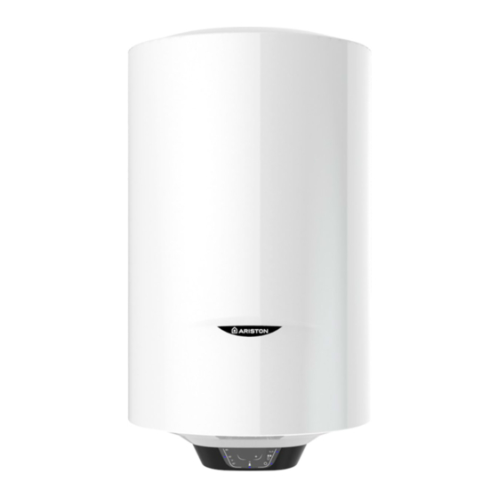
Ariston PRO1 ECO 50V Manual - Página 11
Navegue en línea o descargue pdf Manual para Calentador de agua Ariston PRO1 ECO 50V. Ariston PRO1 ECO 50V 19 páginas. Unvented

ELECTRICAL WARNING:
The appliance must be earthed
The electrical installation must be in line with the current I.E.E. wiring regulations. A mains supply of 240 VAC 3 kW (13
amps) is required (Fig. 2)
Heat resisting cable, round 3 core 1.5 mm (to BS 6141 table 8) should be used to connect to the electrical supply through
either:
- a 13 amp socket to BS 1363; or
- a double pole fused isolating switch with a contact separation of 3 mm minimum on each pole.
Flexible cables are colour coded as follows:
Brown ........................................................ live
Blue ............................................................ neutral
Green and yellow ............................... earth
Safety relay 1
On/Off button
Temperature Adjustment
L
Temperature Visualisation
127-240Vac
Manual Reset
Input
N
Safety relay 2
On/Off button
Temperature Adjustment
Temperature Visualization
Manual Reset
E
To enter into the terminal compartment unscrew the 2 screws on the cover.
(To access the screws, remove the decorative caps on the front control access panel).
It is mandatory, before installing the appliance, to perform an accurate control of the electrical system by verifying
compliance with current safety standards, which is adequate for the maximum power absorbed by the water heater
(refer to the data plate) and that the section of the cables for the electrical connection is suitable and complies with local
regulations. The manufacturer is not liable for damage caused by lack of grounding or anomalous power supply. Before
starting up the appliance, check that the power rating matches that given on the nameplate.
The use of multiplugs, extensions or adaptors is strictly prohibited.
It is strictly forbidden to use the piping from the plumbing, heating and gas systems for the appliance earthing con-
nection. If the appliance is supplied with a power supply cable, should the latter need replacing, use a cable featuring
the same characteristics . The power cord must be routed into the hole in the back of the appliance and connected to
the thermostat terminals (M Fig. 4).
The appliance must be grounded with a cable (yellow/green and longer than the phase cable) connected to the termi-
nals marked
(G Fig. 4).
Functional relay 1
Heating element
NTC 1
NTC 2
User Interface
CPU
R1
Sensor
NTC 1
Fig. 2
wiring diagram
NTC 2
