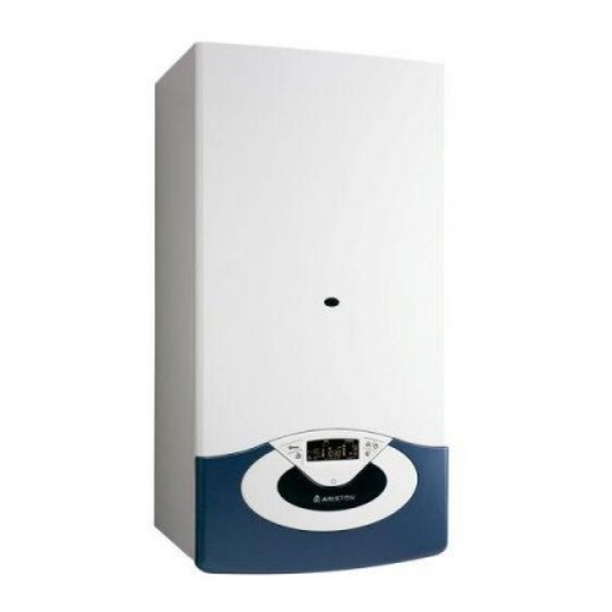
Ariston GENUS 24 FF Instrucciones de instalación y mantenimiento - Página 26
Navegue en línea o descargue pdf Instrucciones de instalación y mantenimiento para Caldera Ariston GENUS 24 FF. Ariston GENUS 24 FF 44 páginas. Wall-hung gas boiler
También para Ariston GENUS 24 FF: Manual del usuario (21 páginas)

messa in funzione
Funzione Auto
Funzione che permette alla caldaia di adattare autonomamente
il proprio regime di funzionamento (temperatura degli elementi
scaldanti) alle condizioni esterne per raggiungere e mantenere le
condizioni di temperatura ambiente richieste.
A seconda delle periferiche connesse
e del numero delle zone gestite, la
caldaia regola autonomamente la
temperatura di mandata.
Provvedere quindi al settaggio dei
vari parametri interessati (vedi menu
regolazioni).
Per attivare la funzione premere il
tasto A
.
UTO
Per
maggiori
informazioni
consultare
il
Manuale
Termoregolazione di ARISTON.
Esempio 1:
I
(
MPIANTO SINGOLA ZONA
ALTA TEMPERATURA
In questo caso è necessario impostare i seguenti parametri:
4 2 1 - Attivazione Termoregolazione tramite sensori
- selezionare 01 = Dispositivi On/Off
2 4 4 - Boost Time (opzionale)
può essere impostato il tempo di attesa per l'incremento
a step di 4°C della temperatura di mandata. Il valore varia a
seconda del tipo di impianto e di installazione.
Se il Boost Time è = 00 tale funzione non è attiva
Esempio 2:
I
(
MPIANTO SINGOLA ZONA
ALTA TEMPERATURA
.
SONDA ESTERNA
In questo caso è necessario impostare i seguenti parametri:
4 2 1 - Attivazione Termoregolazione tramite sensori
- selezionare 03 = solo sonda esterna
4 2 2 - Selezione curva termoregolazione
- selezionare la curva interessata in base al tipo di impianto, di
installazione, di isolamento termico dell'edifi cio etc..
4 2 3 - Spostamento parallelo curva se necessario, che permette di
spostare parallelamente la curva aumentando o diminuendo
la temperatura di set-point (modifi cabile anche dall'utente,
tramite la manopola di regolazione della temperatura
riscaldamento che con la funzione auto attivata, svolge la
funzione di spostamento parallelo della curva).
Esempio 3:
I
(
MPIANTO SINGOLA ZONA
ALTA TEMPERATURA
MANAGER +
.
SONDA ESTERNA
In questo caso è necessario impostare i seguenti parametri:
4 2 1 - Attivazione Termoregolazione tramite sensori
- selezionare 4 = sonda esterna + sonda ambiente
4 2 2 - Selezione curva termoregolazione
- selezionare la curva interessata in base al tipo di impianto, di
installazione, di isolamento termico dell'edifi cio etc..
4 2 3 - Spostamento parallelo curva se necessario, che permette di
spostare parallelamente la curva aumentando o diminuendo
la temperatura di set-point (modifi cabile anche dall'utente
tramite l'encoder che, con la funzione A
funzione di spostamento parallelo della curva)
4 2 4 - Infl uenza del sensore ambiente
- permette di regolare l'infl uenza del sensore ambiente sul
calcolo della temperatura di set-point mandata (20 = massima
0 = minima)
26
Sensore esterno
External sensor
di
)
T
A
/
CON
ERMOSTATO
MBIENTE ON
OFF
)
T
A
/
CON
ERMOSTATO
MBIENTE ON
)
C
R
CLIMA
CON
ONTROLLO
EMOTO
attivata, svolge la
UTO
commissioning
Auto function
This is a function which enables the boiler to automatically adapt its
operation routine (the temperature of the heating elements) in line
with the outdoor conditions, in order to achieve and maintain the
requested room temperature conditions.
Sensori interni
Room sensor
Riscaldamento
Example 1:
.
S
(
INGLE ZONE SYSTEM
HIGH
In this case the following parameters must be set:
4 21 - Activation of temperature adjustment using sensors
- Select 04 = Basic temperature adjustment
2 44 - Boost Time (optional)
The wait time for the fl ow temperature increase in steps of 4°C
may be set. The value varies according to the type of system
and installation.
If the Boost Time value = 00 the function is not activated.
Example 2:
+
S
(
OFF
INGLE ZONE SYSTEM
HIGH
:
SENSOR
In this case the following parameters must be set:
4 21 - Activation of temperature adjustment using sensors
- Select 01 = outdoor sensor only
4 22 - Temperature adjustment curve selection (see page 25)
- Select the relevant curve according to the type of system,
installation, heat insulation used in the building, etc.
4 23 - Perform a parallel curve shift if necessary, increasing or
decreasing the set-point temperature (this may also be
modifi ed by the user, using the heating temperature
adjustment knob, which, with the Auto function activated, is
used to shift the curve in a parallel manner).
Example 3:
S
(
INGLE ZONE SYSTEM
HIGH
OUTDOOR SENSOR
In this case the following parameters must be set:
4 21 - Activation of temperature adjustment using sensors
- select 0 = outdoor sensor + room sensor
4 22 - Temperature adjustment curve selection (see page 25)
- Select the relevant curve according to the type of system,
installation, heat insulation used in the building, etc
4 23 - Perform a parallel curve shift if necessary, increasing or
decreasing the set-point temperature. (This may also be
changed by the user by the encoder which, with the Auto
function activated, is used to shift the curve in a parallel
manner.)
4 24 - Infl uence of room sensor
- used to adjust the infl uence the room temperature has
on the calculation of the set-point fl ow temperature (20 =
maximum, 0 = minimum).
Depending on the peripheral units
connected and the number of zones
controlled, the boiler adjusts its fl ow
temperature automatically.
The
various
parameters should therefore be set
(see adjustments menu).
To activate the function, press the
A
button.
UTO
For further information please
refer to the ARISTON temperature
adjustment manual.
-
)
/
T
TEMPERATURE
WITH ON
OFF ROOM
-
)
/
T
TEMPERATURE
WITH ON
OFF ROOM
-
)
REMOCON
TEMPERATURE
WITH
corresponding
:
HERMOSTAT
+
HERMOSTAT
OUTDOOR
C
+
REMOTE
ONTROL
