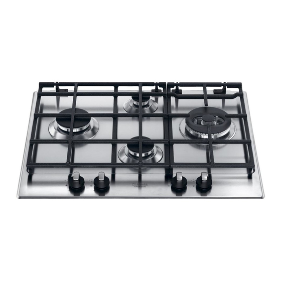
Ariston PC 640 TX AUS Manual de instrucciones - Página 8
Navegue en línea o descargue pdf Manual de instrucciones para Placa Ariston PC 640 TX AUS. Ariston PC 640 TX AUS 32 páginas.

• Cabinets installed adjacent to the hood must be at least
AUS
420 mm above the hob,
600mm min.
Range hoods
Range hoods and overhead exhaust fans must be installed
according to manufacturers' instructions but in no case shall
clearance from hob burners be less than 650 mm for range
hoods and 750 mm for overhead exhaust fans.
• If the hood is installed below a wall cabinet, the latter
must be at least 700 mm (millimetres) above the surface
of the hob.
Fitting the cooktop above an oven
When installing the cooktop above an oven, both the
electricity supply cable and the gas pipe or flexible hose
must not touch hot parts of the oven housing.
When installing above a built-under oven without forced
cooling ventilation, suitable air vents should be provided for
(inlet at least 200 cm² from the bottom, outlet at least 120
cm² from the top part) to allow adequate ventilation inside
the housing unit.
Also a wooden panel should be installed beneath the hob
as insulation, positioning it at a minimum distance of 15 mm
from the hob housing.
Before the installation remove the grids and burners from
the hob and turn it upside down, making sure you don't
damage the thermocouples and spark plugs.
For proper application make sure the surfaces to be sealed
are clean, dry and free of any grease/oil.
• The installation cavity should have the dimensions
indicated in the figure. Fastening hooks are provided,
allowing you to fasten the hob to tops that are between 20
and 40 mm thick. To ensure the hob is securely fastened
to the top, we recommend you use all the hooks provided.
8
The following minimum clearances
to combustible materials must be
observed:
• Minimum clearance from edge
of burner to side wall must be 200
mm.
• Minimum clearance from edge of
burner to rear wall must be 55 mm.
Apply the seals that come with
the appliance along the outer
edges of the hob to prevent any
passage of air, humidity and
water (see Figure).
555 mm
Hook fastening diagram
Hooking position
for top H=20mm
Hooking position
for top H=40mm
! Use the hooks contained in the "accessory pack".
• Where the hob is not installed over a built-in oven, a
wooden panel must be installed as insulation. This must
be placed at a minimum distance of 20 mm from the lower
part of the hob.
Ventilation
To ensure adequate ventilation, the back panel of the cabinet
must be removed. It is advisable to install the oven so that it
rests on two strips of wood, or on a completely flat surface
with an opening of at least 45 x 560 mm (see diagrams).
Electrical connection
Hobs equipped with a three-pole power supply cable are
designed to operate with alternating current at the voltage and
frequency indicated on the data plate (this is located on the
lower part of the appliance). The earth wire in the cable has a
green and yellow cover. If the appliance is to be installed above
a built-in electric oven, the electrical connection of the hob and
the oven must be carried out separately, both for electrical
safety purposes and to make extracting the oven easier.
Connecting the supply cable to the mains
Install a standardised plug corresponding to the load
indicated on the data plate.
The appliance must be directly connected to the mains
using an omnipolar circuit-breaker with a minimum contact
opening of 3 mm installed between the appliance and the
mains. The circuit-breaker must be suitable for the charge
Hooking position
for top H=30mm
Front
Back
