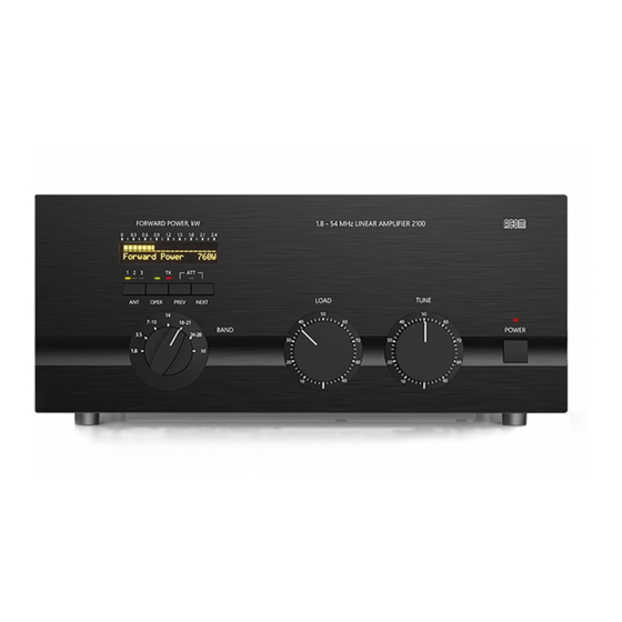
Acom 2100 Esquemas - Página 15
Navegue en línea o descargue pdf Esquemas para Amplificador Acom 2100. Acom 2100 20 páginas. External radio frequency power amplifier
También para Acom 2100: Manual de instalación (6 páginas)

TV1
ANG
A
R1
R2
1
2
3
4
5
160
160
2W
2W
B
Shown f or 240V
LV Transf . Settings:
A
100V
1
2
3
4
5
110V
B
A
1
2
3
4
5
120V
B
A
1
2
3
4
5
200V
B
A
210V
1
2
3
4
5
220V
B
A
230V
1
2
3
4
5
240V
B
HV Transformer Settings:
Mains
8 4
U V W W
X X X X
100V
8 4
0 - 3 7
1 2 5 6
110V
8 4
0 - 2 6
1 3 5 7
120V
8 4
0 - 1 5
2 3 6 7
200V
8 4
7 0 3 -
1 2 5 6
210V
8 4
7 0 2 -
1 3 5 6
220V
8 4
6 0 2 -
1 3 5 7
230V
8 4
6 0 1 -
2 3 5 7
240V
8 4
5 0 1 -
2 3 6 7
- LV Transf .
D1
2x10.5V
18VA
D1-D4
4x1N4002
C6
47n
100V
D2
F1
200mA
SB
W
W
C1
C2
2.2n/Y 2
2.2n/Y 2
U
0
C3
10n/X2
V
R3
1M/0.5W
Mains AC
M1
M2
F2,F3
20
Amp
15-16
Notes:
Amp
1. Tap 4 always to terminal 4.
2. Tap 8 always to terminal 8.
3. Four depot terminals X
equivalent each other.
+24VP
(sht.2)
D3
C7
C8
470uF
R6
2.7k/0.5W
35V
47n
100V
D4
C5
C9
3300uF
100n
25V
K2A
(Step)
AZ733
F2
R4A
2ASB
(On)
10/10W
C4A
R5A
100n/630V
100/1W
n/c
K2B
(Step)
AZ733
F3
R4B
2ASB
10/10W
C4B
R5B
100n/630V
100/1W
n/c
n/c
n/c
X X X X - Depot
MAINS 1/5
D5
K1
1N4002
793-P-1C
U1
7805
Bottom View
In
C
Out
C11
C10
10uF
100n
10V
HV Transf ormer:
K1A
AZ733
1
4
10V
2
10V
3
100V
4
5
10V
6
10V
7
K1B
(ON)
AZ733
100V
8
8
(JP5:6)
RFC1
(sht.4)
10uH
+24VPI
C12
47n/100V
(JP7:4)
RFC2
(sht.4)
22uH
*PWRON
C13
47n/100V
RFC3
(sht.4)
2.2uH/1A
+5VI
(JP5:8,9)
+5V
(sht.2,3)
J1
2050Va
Fast-On
2510V
J2
2050Vb
JP2
CST100-8
o
120Va
1
2
120V
120Vb
3
4
5
305Va
6
305V
7
305Vb
8
o
JP1
Sl156-3
19Va
1
19V
19VCT
2
19Vb
19V
3
H1
Fast-On
6Va
7V
H2
6Vb
