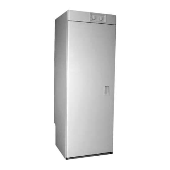
Whirlpool DryAire LMA1053L Manual - Página 3
Navegue en línea o descargue pdf Manual para Secadora Whirlpool DryAire LMA1053L. Whirlpool DryAire LMA1053L 32 páginas. Drying cabinet
También para Whirlpool DryAire LMA1053L: Manual (32 páginas)

GENERAL............................................................................................................................................. 1-1
Safety First ...................................................................................................................................... 1-1
Model & Serial Number Designations ............................................................................................. 1-2
Model & Serial Number Label & Wiring Diagram Locations ........................................................... 1-3
Specifications .................................................................................................................................. 1-4
Whirlpool DryAire Drying Cabinet Warranty ................................................................................... 1-5
INSTALLATION INFORMATION ......................................................................................................... 2-1
Mounting The Cabinet ..................................................................................................................... 2-1
Changing The Door Swing .............................................................................................................. 2-2
PRODUCT OPERATION ...................................................................................................................... 3-1
Drying Clothes ................................................................................................................................. 3-1
Controls & Switches ........................................................................................................................ 3-2
COMPONENT ACCESS ....................................................................................................................... 4-1
Component Locations ..................................................................................................................... 4-1
Removing The Component Panel ................................................................................................... 4-2
Removing The High Limit Thermostat And The Heater .................................................................. 4-3
Removing The Timer ...................................................................................................................... 4-4
Removing The Blower Assembly, The Thermostat & Temperature Sensor ................................... 4-5
Removing The Relay ...................................................................................................................... 4-6
Removing The Push-To-Start & Door Switches ............................................................................. 4-7
Removing The Component Panel-Mounted Terminal Block........................................................... 4-8
Removing The Power Cord And Cabinet-Mounted Terminal Block ............................................... 4-9
Removing The Cabinet Door ........................................................................................................ 4-10
COMPONENT TESTING ...................................................................................................................... 5-1
High Limit Thermostat ..................................................................................................................... 5-1
Heater ............................................................................................................................................. 5-1
Fan Motor ........................................................................................................................................ 5-2
Thermostat ...................................................................................................................................... 5-2
Timer ............................................................................................................................................... 5-3
Door & Push-To-Start (PTS) Switches............................................................................................ 5-3
WIRING DIAGRAM .............................................................................................................................. 6-1
TABLE OF CONTENTS
- iii -
Page
