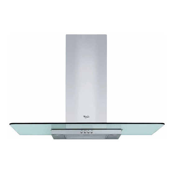
Whirlpool AKR 555/1/IX Manual - Página 6
Navegue en línea o descargue pdf Manual para Campana de ventilación Whirlpool AKR 555/1/IX. Whirlpool AKR 555/1/IX 11 páginas.

INSTALLATION - ASSEMBLY INSTRUCTIONS
The instructions below, to be carried out in the order in which they are numbered, refer to the figures (with the same step numbers) given on the last pages of
this manual.
N.B.: The size and/or shape of the hood may differ from that illustrated, nonetheless the installation procedure remains the same.
1. Mark a line on the wall right up to the ceiling, corresponding to the centre-line of the hood.
N.B. (60cm wide model only): Cut the template along the dotted lines 60.
2. Attach the hole diagram to the wall (using adhesive tape): the vertical centre line printed on the hole diagram must match the centre line drawn on the
wall, and the lower horizontal edge of the hole diagram must match the lower edge of the hood.
Drill 3 holes.
3. Remove the hole diagram, and insert plugs and screws as shown.
4. Partially tighten the screws.
5. Fit the flue support bracket to the wall and against the ceiling. Drill and insert the wall plugs as shown. Fix the bracket.
6. For Extractor Version only - rear exhaust outlet: Make an opening on the wall for the exhaust pipe.
7. For Extractor Version only - ceiling exhaust outlet: Make an opening in the ceiling for the exhaust pipe.
8. Prepare the electrical connection to the mains power supply.
9. For Filter Version only: Fix the deflector to the flue support bracket.
10. Fit the decorative casing with screws and bushings as shown (the screenprinted side against the hood).
N.B.: The size and/or shape of the decorative casing may differ from that illustrated, nonetheless the installation procedure remains the same.
11. Remove the grease filter/s.
12. Hook the hood to the wall.
13. Adjust the hood horizontally.
14. Adjust the distance between the hood and the wall.
15. Fix the hood to the wall with screws as shown.
16. Connect an exhaust pipe to the collar; the fumes must be ducted to the outside (extractor version) or towards the deflector (filter version). Carry out the
electrical connection to the mains power supply.
Note (For Extractor Version only): the hood comes provided with a push-fit multiconnector which attaches to the exhaust aperture of the hood, for use with
Ø125 or Ø120 pipes.
17. Prepare the top flue with the slots visible (Filter Version) or hidden (Extractor Version) and fit the flues over the extractor unit, engaging them in their seat
above the hood.
18. Slide the top section upwards and fix the flues with the screws as shown.
19. Fit the carbon filter (Not provided, to be ordered separately - only for Filter Version ) andrefit the grease filter/s.
Check for correct hood operation, referring to the hood description and use section.
GB13
