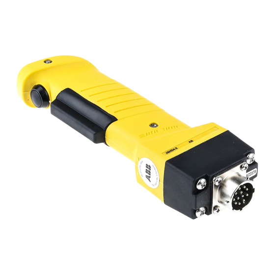
ABB JSHD4 Manual de instrucciones original - Página 9
Navegue en línea o descargue pdf Manual de instrucciones original para Unidad de control ABB JSHD4. ABB JSHD4 20 páginas. Three-position enabling device

Electrical connections – AD
Bottom part – AD:
8-pole male M12-connector
1 ) S2 – Common
2 ) S1, S3, S4 – Common*
3 ) S3 – Actuated
4 ) S4 – Actuated
5 ) S1 – Actuated
Anti-tamper – Common
6 ) S2 – Actuated
7 ) 0 VDC (anti-tamper, LED 1, LED 2)
8 ) Anti-tamper – Operator detected
* NB: COM signal must be +24 VDC for proper LED and anti-
tamper PCB function.
NB: 8-pole male M12 connector with wiring suitable for safety relays in the RT-series and Pluto safety-PLC. A
jumper must be placed over pins 14-16 on the 2x8 Molex connector if an anti-tamper PCB is not used.
Electrical connections – AE
Bottom part – AE:
8-pole male M12-connector
1 ) S2 – Common
2 ) S1 – Common*
3 ) S2 – Actuated
0 VDC (LED 1, LED 2)
4 ) S1 – Actuated
5 ) E1 (E-stop channel 1)
6 ) E1 (E-stop channel 1)
7 ) E2 (E-stop channel 2)
8 ) E2 (E-stop channel 2)
* NB: COM signal must be +24 VDC for proper LED function.
NB: 8-pole male M12 connector with wiring suitable for safety relays in the RT-series. An emergency stop push
button is attached on the bottom part and is connected to pins 13-16 on the 2x8 Molex connector. Anti-tamper PCB
or extra push buttons are not possible for this unit.
2TLC172052M0201, rev. A
2011-10-06
1
2
3
Male pins in 2x8
Molex male
8-pole male
M12-connector
1
2
3
1
7
6
M12 8-pole male
seen from cable
side
1
2
3
Male pins in 2x8
Molex male
8-pole male
M12-connector
1
2
3
9
4
5
6
7
8
9
4
5
6
7
8
2
2
1
8
8
3
3
7
4
4
6
5
5
M12 8-pole female
seen from cable
side
4
5
6
7
8
9
4
5
6
7
8
1
2
8
7
6
5
M12 8-pole male
seen from cable
side
10
11
12
13
14
15
16
Extra jumper.
Required if no anti-
tamper is used.
10
11
12
13
14
15
16
2
1
8
3
3
7
4
4
6
5
M12 8-pole female
seen from cable
side
www.jokabsafety.com
