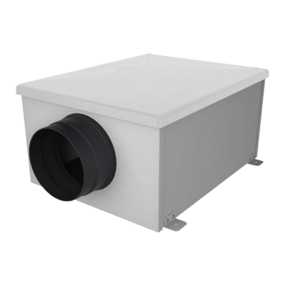
aerauliqa QBX EC Manual de instalación - Página 4
Navegue en línea o descargue pdf Manual de instalación para Ventilador aerauliqa QBX EC. aerauliqa QBX EC 20 páginas. Centrifugal box fan

VERSIONS
QBX...AC 3V
The unit is equipped with a 3 speed AC motor and back-curved centrifugal impeller.
QBX...EC
The unit is equipped with EC motor, for energy saving and forward-curved centrifugal impeller.
QBX...EC PLUS
The unit is equipped with EC motor, for energy saving and back-curved centrifugal impeller.
OPERATION
QBX...AC 3V
Single speed operation
The unit is activated by means of a remote ON/OFF switch or light switch.
Wiring diagram: Fig.5A
Three speed operation with SEL-3V speed selector (accessory on request)
The unit runs at the speed selected by turning the knob of the SEL-3V speed selector (fig.8).
Wiring diagram: Fig.5B
QBX...EC and QBX..EC PLUS
Single speed operation
The unit runs at the speed set by turning the integral trimmer "V1" in the terminal box.
This is the default factory setting.
Wiring diagram: Fig.6A – Dip switch configuration: 0000 (Fig.6F)
Two speed operation
The unit runs continuously at the speed set by turning the integral trimmer "V1" in the terminal box and can be boosted at high speed, which is set
by turning the integral trimmer "V2" in the terminal box. Boost is activated, when needed, by means of a remote two-position switch (not supplied)
or by means of remote sensors (SEN-HY, SEN-CO2 or SEN-PIR), which are accessories on request.
Wiring diagram: Fig.6B – Dip switch configuration: 1000 (Fig.6F)
Variable speed operation with CTRL-M remote manual controller (accessory on request)
The unit runs at the speed set by turning the knob of the 149-SEN-CTRLM remote manual control panel (accessory, fig.7).
Wiring diagram: Fig.6C – Dip switch configuration: 0100 (Fig.6F)
Variable speed operation through external domotic (BMS) system or ballast potentiometer
The unit runs at the speed set by turning the knob of an external 1-10V ballast potentiometer or set by an external 1-10V signal from a domotic
(BMS) system.
Wiring diagram: Fig.6D – Dip switch configuration: 0110 (Fig.6F)
Three speed operation with SEL-3V speed selector (accessory on request)
The unit runs at the speed selected by turning the knob of the SEL-3V speed selector (fig.8).
Speed 1 is set by turning the integral trimmer "V1" in the terminal box.
Speed 2 is set by turning the integral trimmer "V2" in the terminal box.
Speed 3 is the maximum speed achievable by the unit.
Wiring diagram: fig.6E - Dip switch configuration: 100 (fig.6F)
MAINTENANCE
Make sure the mains supply of the unit is disconnected before performing any maintenance.
The maintenance must be carried out by a qualified technician and in accordance with local rules and regulations.
STANDARD CONFORMITY
2014/35/EU Low Voltage Directive (LVD)
2014/30/EU Electromagnetic Compatibility (EMC),
in conformity with the following standards:
Electrical Safety
EN60335-1(2008); EN 60335-2-80(2005); EN 60335-2-80/A2(2009)
Electromagnetic Compatibility
EN 55014-1(2006)+A1(2009); EN 55014-2(1997)+A1(2001)+A2(2008)+IS1(2007)
EN 61000-3-2(2006)+A1(2009)+A2(2009); EN 61000-3-3(2008).
4
