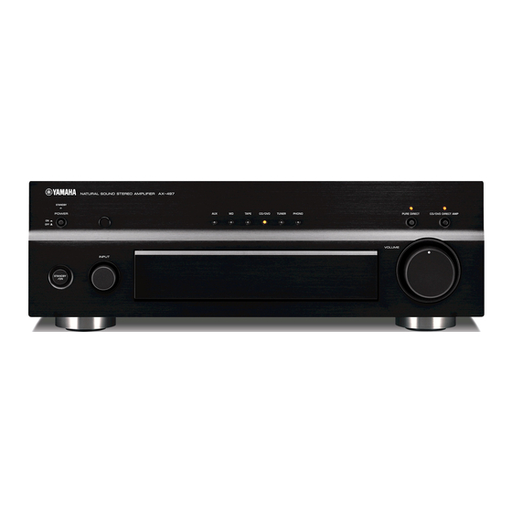
Yamaha AX-397 Manual de servicio - Página 2
Navegue en línea o descargue pdf Manual de servicio para Amplificador Yamaha AX-397. Yamaha AX-397 36 páginas. Yamaha ax-397 stereo amplifier service manual
También para Yamaha AX-397: Manual del usuario (23 páginas), Manual del usuario (24 páginas)

AX-397
TO SERVICE PERSONNEL
1. Critical Components Information
Components having special characteristics are marked Z
and must be replaced with parts having specifications equal
to those originally installed.
2. Leakage Current Measurement (For 120V Models Only)
When service has been completed, it is imperative to verify
that all exposed conductive surfaces are properly insulated
from supply circuits.
Meter impedance should be equivalent to 1500 ohms shunted
by 0.15µF.
"CAUTION"
"F151, F152 : FOR CONTINUED PROTECTION AGAINST RISK OF FIRE, REPLACE ONLY WITH SAME TYPE 6A, 125V FUSE."
A
V
CAUTION
F151, F152 : REPLACE WITH SAME TYPE 6A, 125V FUSE.
ATTENTION
F151, F152 : UTILISER UN FUSIBLE DE RECHANGE DE MEME TYPE DE 6A, 125V.
WARNING: CHEMICAL CONTENT NOTICE!
The solder used in the production of this product contains LEAD. In addition, other electrical/electronic and/or
plastic (where applicable) components may also contain traces of chemicals found by the California Health and
Welfare Agency (and possibly other entities) to cause cancer and/or birth defects or other reproductive harm.
DO NOT PLACE SOLDER, ELECTRICAL/ELECTRONIC OR PLASTIC COMPONENTS IN YOUR MOUTH FOR
ANY REASON WHATSOEVER!
Avoid prolonged, unprotected contact between solder and your skin! When soldering, do not inhale solder fumes
or expose eyes to solder/flux vapor!
If you come in contact with solder or components located inside the enclosure of this product, wash your hands
before handling food.
About Lead Free Solder /
The P.C.B.s installed in this unit are soldered using the fol-
lowing solder.
Among some types of lead free solder currently available, it
is recommended to use one of the following types for the
repair work.
• Sn + Ag + Cu (tin + silver + copper)
• Sn + Cu (tin + copper)
• Sn + Zn + Bi (tin + zinc + bismuth)
2
WALL
OUTLET
REFLOW
SMT
Side A
Solder Dip
Side B
FLOW
MI
EQUIPMENT
UNDER TEST
INSULATING
TABLE
Leakage current must not exceed 0.5mA.
Be sure to test for leakage with the AC plug in both
polarities.
Process
Process
AC LEAKAGE
TESTER OR
EQUIVALENT
