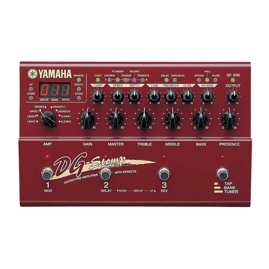
Yamaha DG-Stomp Manual de servicio - Página 17
Navegue en línea o descargue pdf Manual de servicio para Amplificador Yamaha DG-Stomp. Yamaha DG-Stomp 43 páginas. Guitar pre-amplifier with effects
También para Yamaha DG-Stomp: Manual complementario (1 páginas), Manual del usuario (32 páginas)

- 1. Specifications
- 2. Panel Layout
- 3. Block Diagram
- 4. Circuit Board Layout
- 5. Wiring
- 6. Disassembly Procedure
- 7. Lsi Pin Description
- 8. IC Block Diagram
- 9. Circuit Boards
- 10. Test Program
- 11. Error Messages
- 12. MIDI Implementation Chart
- 13. Parts List
- 14. Guitar Pre-Amplifier with Effects
- 15. Overall Assembly
- 16. Electrical Parts
YM3437C-F (XM530A00) DIT2 (Digital Format Interface Transmitter)
PIN
NAME
I/O
NO.
1
Vss
Ground
2
MCLK
I
Master clock input
3
DM0
I
DIN/BCLK/WCLK format select
4
DM1
I
DM1,DM0=0,0 DSP,LDSP (64 bit,LSB first)
DM1,DM0=0,1stereo,DSP (64 bit,MSB first)
DM1,DM0=1,0 DSP2 (128 bit,MSB first)
DM1,DM0=1,1 BB (64 bit,MSB first)
5
RES
I
System reset
6
WCIN
I
Word clock input
7
DIN
I
Digital audio serial data input
8
V
Power supply (+5 V)
DD
AK4520A-VF-E2 (XT802A00) DAC & ADC
PIN
NAME
I/O
NO.
1
VREFH
I
Positive Voltage Reference Input, VA
2
VREFL
I
Negative Voltage Reference Input, AGND
3
AINR+
I
Rch Analog Positive Input
4
AINR-
I
Rch analog Negative Input
5
AINL+
I
Lch Analog Positive Input
6
AINL-
I
Lch analog Negative Input
7
VA
-
Analog Power Supply
8
AGND
-
Analog Ground
9
DIF0
I
Audio Data Interface Format
10
DIF1
I
Audio Data Interface Format
11
LRCK
I
Input/Output Channel Clock
12
SCLK
I
Audio Serial Data Clock
13
SDTI
I
Audio Serial Data Input
14
SDTO
O
Audio Serial Data Output
FUNCTION
FUNCTION
PIN
NAME
I/O
NO.
9
MUTE
I
Mute
10
VFL
I
Validity flag
11
CCK
I
C,U bit clock input/C bit data input
12
CIN
I
C,U bit data input/U bit data input
13
CLD
I
End of C,U bit input/16,20 bit/24 bit select
14
CNTR
I
32 bit counter reset/Top of block
15
CSM
I
Channel status input mode select
CSM=0 Asynchronous mode
CSM=1 Synchronous mode
16
DOUT
O
Digital interface formatted data output
PIN
NAME
I/O
NO.
15
MCLK
I
Master Clock Input
16
DEM0
I
De-emphasis Frequency Select
17
DEM1
I
De-emphasis Frequency Select
18
TST3
I/O
19
TST2
I/O
Test Pins (Pull Down Pins)
20
TST1
I
21
VD
-
Digital Power Supply
22
DGND
-
Digital Ground
23
/PWDA
I
DAC power-Down Mode
24
/PWAD
I
ADC power-Down Mode
25
CMODE
I
Master Clock Select ("H":384 fs,"L":256 fs)
26
AOUTL
O
Lch Analog Output
27
AOUTR
O
Rch Analog Output
28
VCOM
O
Common Voltage Output, VA/2
DG-Stomp
DM: IC17
FUNCTION
DM: IC104
FUNCTION
17
