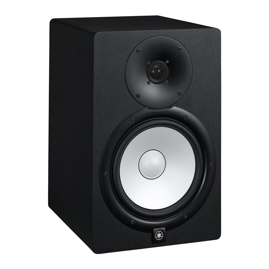
Yamaha HS50M Manual de servicio - Página 9
Navegue en línea o descargue pdf Manual de servicio para Sistema de altavoces Yamaha HS50M. Yamaha HS50M 27 páginas. Hs series powered monitor speaker
También para Yamaha HS50M: Manual del usuario (17 páginas), Manual del usuario (16 páginas)

HS80M
4-3
Unsolder soldered parts (22 locations) on the pat-
tern side of IC801 and IC802. (Photo. 1)
4-4
Remove the two (2) screws marked [A] and remove
the heat sink with IC801 and IC802. (Photo. 1)
Remove the two (2) screws marked [B] and remove
IC801 and IC802. (Photo. 1)
4-5
Remove the four (4) screws marked [C], remove the
AMP mounting bracket. The AMP circuit board can
then be removed. (Photo. 1)
HEAT SINK
HEAT SINK
SPACER
SPACER
AMP mounting BRACKET
AMP mounting BRACKET
AMP
AMP
[B]
[B]
[C]
[C]
Photo. 1
5.
INPUT Circuit Board
(Time required: about 3 minutes)
5-1
Remove the rear panel assembly. (See procedure 3.)
5-2
Remove the four (4) screws marked [110] and the
screw marked [115]. (Fig. 3)
5-3
Remove the LEVEL knob, the hexagonal nut [E] and
washer [D]. (Fig. 3, Photo. 5)
5-4
Remove the hexagonal nut [F] on the phone type in-
put connector. The INPUT assembly can then be re-
moved. (Photo. 5)
5-5
Remove the three (3) screws marked [G] and remove
the case PWB. (Photo. 3)
The Input circuit board can then be removed.
*
The case PWB is not a component of the INPUT cir-
cuit board. When replacing the INPUT circuit board,
remove the case PWB and reuse it.
[A]
AMP mounting BRACKET
AMP mounting BRACKET
AMP
AMP
IC802
IC802
[C]
[C]
IC801
IC801
AMP circuit board
AMP circuit board
AMP
AMP
<AMP Unit>
CASE PWB
CASE PWB
[G]
[G]
Photo. 3
HS80M/HS50M
INPUT Circuit Board
INPUT Circuit Board
INPUT
INPUT
Photo. 2
<INPUT Assembly>
9
