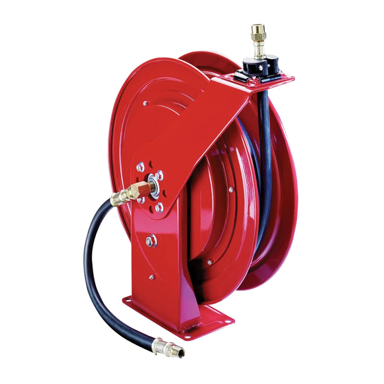
Alemite 7334-B Manual de servicio - Página 9
Navegue en línea o descargue pdf Manual de servicio para Herramientas Alemite 7334-B. Alemite 7334-B 20 páginas. Heavy-duty hose reels

Assembly
NOTE
Prior to assembly, certain components
require lubrication. Refer to tables
and for details.
Pawl assembly
NOTE
Refer to figs. , page and
IPB, page for component
identification on assembly procedures.
Install pawl shaft () [threaded end first]
into the inside of base assembly ().
Apply threadlocker to the threads of the
pawl shaft.
Screw nut () onto the pawl shaft.
. Tighten the nut from to ft.lbf
(57 - 65 nm).
. Make sure to hold the pawl shaft
stationary.
Install pawl () [flat side first] onto the
pawl shaft.
Install washer (), wave spring (),
and additional washer () onto the pawl
shaft.
Components lubricate in clean oil.
Item
Description
O-ring,
/
in ID x
/
7
1
8
16
Seal,
/
in ID x
/
in OD
1
3
2
4
Seal,
/
in ID x
/
in OD
3
3
8
4
Components lubricated in lithium grease
Item Description
O-ring,
/
in ID x
/
in OD
1
5
2
8
Cavity in swivel body
O-ring,
/
in ID x
/
in OD
1
11
2
16
Hooks of pawl spring
Wave spring
Bearing surface of pawl shaft
Ratchet teeth on power spring assembly
Install retaining ring () onto the pawl
shaft.
Install pawl spring () into the eye on
the pawl (→ fig. , page For proper
orientation).
Install screw () into the large diameter
end of pawl spring sleeve ().
Install the screw and sleeve assembly
through the pawl spring and into the
base and shaft assembly.
Install nut () onto the screw.
. Tighten the nut securely.
Base and hose guide assembly
Install bolts () into shaft and flange
assembly ().
Secure the shaft and flange assembly to
the base assembly with nuts ().
. Tighten the nuts securely in a
criss-cross pattern.
Position hose guide assembly () onto
the bolts in the base assembly.
NOTE
The hose guide assembly can attach to
the base assembly in five () separate
positions. Select the required relationship
of the guide to the mounting plate of the
base assembly.
Table
Secure the hose guide assembly to the
base assembly with nuts ().
. Tighten the nuts securely in a
criss-cross pattern.
Install and seat bearing () onto the
in OD
shaft and flange assembly.
Install and hold woodruff key () into
the shaft of the assembly.
Slide spring arbor () [flat side first]
onto the shaft and onto the woodruff
Table
key.
Sheave and power spring
assembly
Position sheave assembly () bearing
NOTE
Make sure to align the mark on the
power spring assembly with the align-
ment mark on the sheave assembly.
(→ fig. IPB, page ).
Position power spring assembly ()
Secure the power spring assembly to the
Install and seat the power spring and
Install washer () and retaining ring ()
Swivel assemblies
Low-pressure swivel assembly
Do not mix o-rings. O-ring () is slightly
larger in outside diameter than
o-ring ().
Install o-ring () into the threaded end of
Install the swivel body onto swivel stud ().
Install thrust washer () and retainer ()
Push the retainer to expose the groove
Install o-ring () onto the swivel body.
side up.
[at alignment marks] on the sheave
assembly.
sheave assembly using screws and nuts
included with replacement assembly.
. Make sure the screw heads seat
properly into the rib of the sheave.
sheave assembly onto the spring arbor.
. Make sure the end of the power
spring properly engages the cam
on the spring arbor.
. Make sure the ratchet either clears
the pawl or engages properly.
onto the shaft and flange assembly.
CAUTION
swivel body ().
. Install o-ring () into the opposite
end of the swivel body.
[flat side first] onto the swivel stud.
in the swivel stud.
. Install keeper () onto the swivel
stud.
