Alemite 7343 Manual de servicio - Página 5
Navegue en línea o descargue pdf Manual de servicio para Herramientas Alemite 7343. Alemite 7343 8 páginas. High capacity twin hose reel

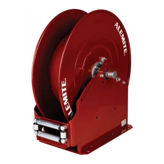
High Capacity Twin Hose Reel
7. Remove Bearing Housing (6) and Bearing (7) from the Shaft
and Flange Assembly.
8. Remove the Sheave Assembly from the Base Assembly.
9. Refer to Figures 2 through 4 for further disassembly.
WARNING
Do not attempt to disassemble Power Spring
Assembly (26). Personal injury can occur.
Assemble and Replace
NOTE: Prior to assembly, certain components
require lubrication. Refer to Table 2 for details.
Refer to Figures 2 through 4 for any assembly
not covered below.
Sheave and Arbor Assembly
1. Position the Sheave assembly [w/ Bearing (7) and Bearing
Housing (6)] into Base Assembly (8).
2. Install Shaft (19) through Ratchet (13) and Bearing (7).
3. Install Nuts (3) that secure the Bearing Housing assembly to
the Base Assembly.
• Tighten the Nuts securely.
4. Install Retaining Ring (5) that secures Shaft (19) to the
Bearing.
5. Install Key (21) into the slot of Shaft and Flange Assembly
(20).
6. Slide Spring Arbor (27) [flat side first] onto the Shaft and
Flange Assembly and Key.
7. Install Retaining Ring (5) that secures the Spring Arbor to
the Shaft and Flange Assembly.
Components Lubricated with NLGI 2 EP Lithium Grease
Item No.
Description
2b
Rings, Back-Up
2c
O-Rings, 5/8 " ID x 13/16 " OD
2e
Land surfaces of Swivel Stem
13
Teeth of Ratchet
28
Bearing surface of Pawl Shaft
28
Wave Washer
29
Hooks of Pawl Spring
Components Lubricated in Oil
2f
O-Ring, 7/8 " ID x 1-1/16 " OD
35
O-Ring, 1/4 " ID x 3/8 " OD
Table 2
Lubricated Components
Alemite, LLC
1-800-548-1191-http://[email protected]
Power Spring Assembly
8. Remove Grommet (25) from the Power Spring Assembly.
9. Install Power Spring Assembly (26) onto the Spring Arbor.
• Make sure the hook on the Power Spring's inner coil
properly engages the recess in the Spring Arbor.
Hint: Lift and center the coil within the case dur-
ing installation.
• Use care not to damage the gasket.
10. Align the Screw holes in the Power Spring Assembly with
the Base Assembly.
11. Secure the Power Spring Assembly to the Base Assembly
with Screws (12).
• Tighten the Screws securely in an alternate pattern.
12. Install the Grommet into the case of the Power Spring
Assembly.
13. Screw the Swivel Assembly into the Shaft and Flange
Assembly.
• Tighten Swivel Stem (2e) securely.
NOTE: The Hose Guide Arms can attach to the
Base Assembly in five (5) different positions.
Select the required relationship of the Guide to
the mounting plate of the Base Assembly.
14. Install the Arm and Hose Guide assembly onto the Base
Assembly.
Bench Test
While facing the ratchet side of the reel, turn the reel in a
counterclockwise direction and allow the ratchet to latch onto
Pawl and Shaft Assembly (28).
If the reel does not tension or latch properly, refer to the
Troubleshooting Chart.
Notes
See Figure 3
5
SER 7343
Revision (11-08)
