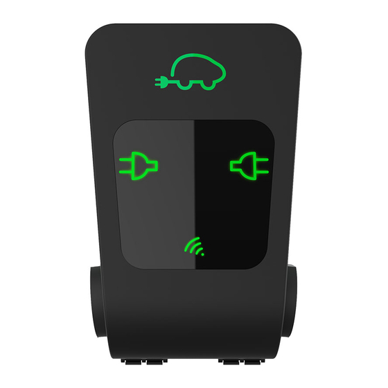
CTEK CGC100 Manual del usuario - Página 3
Navegue en línea o descargue pdf Manual del usuario para Monitor CTEK CGC100. CTEK CGC100 20 páginas.
También para CTEK CGC100: Manual de instalación (8 páginas)

NANOGRID™ grid central
NANOGRID™ grid central is used for parking lots, real estates, industries, etcetera. The NANOGRID™ grid central is
available in two versions:
•
CGC100: Applicable for installations for up to 70 charge points.
•
CGC500: Applicable for installations for up to 500 charge points.
Elevator
The grid central is a separate compact device cabinet that contains a charge control unit, an energy meter and a
transformer measurement equipment. The grid central manages the charging stations and the external loads such as
lighting, ventilation, elevator.
Deployment of the NANOGRID™
Mains
Grid Central
(CGC500™)
INTERNET
Ethernet Switch
Distribution Panel
To install the power and network cables to the stations, refer to the CHARGESTORM CONNECTED 2 USER MANUAL. The
manual is available at https://chargestorm.se/en/manuals/
NOTE: Manuals are also available for older stations, such as the CHARGESTORM CONNECTED 1. Make sure that you
refer to the correct installation manual when you install the power supply and the network cables.
CTEK E-Mobility AB
CTEK GRID
CENTRAL
Lighting
*
*
*Phase rotation
For information about IT-Net installations, refer to "To connect stations used in IT-Net" on page 9.
Installation procedure
NOTE: It is possible to install chargers and at a later step configure and enable a site.
NOTE: To create the correct configuration file, make sure that you have all information about the installation available.
Example of the typical installation procedure:
1.
Do a plan of the phase rotation of the chargers.
2.
Write down the amperage of the protective fuses.
Install the chargers according to the phase rotation plan.
3.
4.
Configure the NANOGRID™ master with the NANOGRID™ file.
5.
Make sure that the installation is correctly done.
To plan the phase rotation
The phase rotation creates an even load on a larger installation site. Many EVs use a 1-phase for charging and thus only
draw current on the L1 in the EVSE outlet. If the phase rotation is not applied, the L1 fuse can easily overload and the fuse
blow.
1.
Divide all the chargers into three groups; RST, STR and TRS.
2.
Install all the chargers in each group with the phase rotation that follows:
a.
RST group with L1, L2, L3
STR group with L2, L3, L1
b.
c.
TRS group with L3, L1, L2
3.
Make sure that you save all the chargebox identities and what group they belong to before the configuration.
Example 20 chargers:
•
RST group: 1, 4, 7, 10, 13, 16, 19
•
STR group: 2, 5, 8, 11, 14, 17, 20
•
TRS group: 3, 6, 9, 12, 15, 18
NANOGRID™ local/grid central configuration
*
™
The NANOGRID
installation must be configured correctly for the load balancing to do the correct decisions and
actions. The most important configuration is the configuration of the NANOGRID™ controller unit. The NANOGRID™
controller unit has two variants:
•
CTEK GRID CENTRAL (CGC): A controller unit that is dedicated to the task of load balancing. The control unit is
usually installed in a separate cabinet.
•
Master Controller Unit (Master): A controller unit that also operates as a regular charging station. The external
surface is typically the same as a controlled charging station.
NOTE: For more information about advanced and optional configuration, refer to "Advanced configuration" on page
7.
The information in this section is applicable to both CGC and Master.
Configuration instructions
3
