Clarke 6460100 Manual de funcionamiento y mantenimiento - Página 7
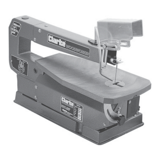
Navegue en línea o descargue pdf Manual de funcionamiento y mantenimiento para Sierra Clarke 6460100. Clarke 6460100 14 páginas. 400mm (16") scroll saw

2.BLADE HOLDER ALIGNMENT
It is important that the blade holders are checked for alignment before use. Misaligned holders
will cause the blade to wander, and reduce the blades' life expectancy.
To check the alignment,
2.1 Loosen the tension on the blade by turning the blade
tension knob (17), two full turns anticlockwise.
2.2 Prise out the table insert (79), by pushing it from
beneath the table with your fingers.
2.3 Apply a slight downward pressure on the upper arm
whilst holding the blade firmly, allowing the pins at
the top of the blade to be disengaged from the
recesses in the upper blade holder (26) - see fig 2. It is
now a simple matter to disengage the blade pins from
the lower blade holder and lift the blade out through
the access hole in the table.
2.4 Remove the side cover (2), by unscrewing thethree
retaining screws, to give access to the lower holder.
2.5 Slacken off the single hex. socket head screws
securing the upper and lower blade holders, (see fig
3), so that the holders move freely, using the hex
socket wrench supplied.
2.6 A metal strip is provided which should be inserted into
the blade slots in both holders, thereby replacing the
blade as shown in fig. 3.
Turn the strip, and therefore the blade holders, in
unison, so that it is in line with the table axis. Carefully
tighten each holder in turn, taking great care not to
alter their positions as you do so.
On completion, replace the side cover, table insert
and blade by reversing the procedure above.
NOTE: If the blade tends to wander during use, re-check this adjustment as it may take one or two attempts
to get it right. Also see page 11 - Straight Line Cutting, for other causes of blade wander.
3. BEVEL ALIGNMENT
To align the bevel indicator, loosen the table bevel lock knob (57), and level the table until it is at
right angles to the blade. Use a small square to be sure that the angle between blade and table
o
is 90
.
NOTE: The metal strip may be used, in place of the blade, if
desired.
When the table is perpendicular to the blade, or metal
strip, tighten the bevel lock knob (57).
Loosen the screw holding the pointer (62), adjust the
pointer to 0
O
, then retighten the screw.
The bevel scale is a convenient indicator, but it is not
guaranteed to be 100% accurate. Where absolute
accuracy is required, always double check with a
protractor before starting a cut.
(see fig. 4)
8
Fig. 2
Fig. 3
Fig..4
