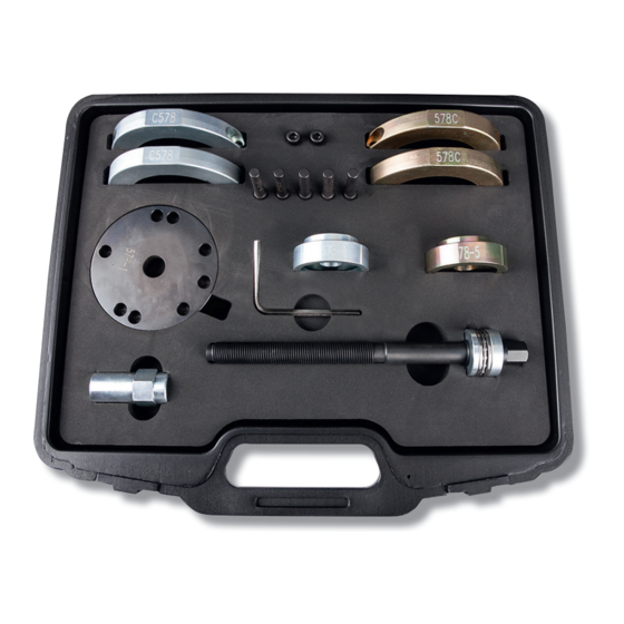
CLAS OM 3426 Manual - Página 6
Navegue en línea o descargue pdf Manual para Equipos de servicio CLAS OM 3426. CLAS OM 3426 8 páginas. Wheel hub bearing tool set

OM 3425
WHEEL HUB BEARING TOOL SET HUB 2.1 Ø72mm
INSTRUCTIONS
Removal
The kit is designed to remove and replace the bearing/ ange in situ
on the vehicle. Refer to manufacturer's documentation for the correct
procedure.
• Remove the brake caliper and disc. Remove the driveshaft.
• Clean the area at the back of the hub prior to removal of the
bearing to prevent dirt and debris jamming the force screw, force
nut and adaptor.
• Assemble the removal clamshells (C) to the bearing/ ange; refer
to diagram (Fig 1), secure with set screws (D) supplied.
• Assemble the four force pins (E) to the force plate (B).
The rubber O-ring on the force pin will secure it in the force plate
socket.
• Offer up the force plate/pin assembly to the clamshells, and t the main force screw through the force plate/
pin assembly.
• From behind, t the extraction adaptor (G) over the end of the force screw. Collar-end in towards force screw -
refer to Fig 1. Take care to line up cut outs with the ABS sensor.
• Secure the assembled tool with the force screw nut (F). Long threaded end of force screw nut in towards force
screw - refer to Fig 1.
• Lubricate the force screw threads with black molybdenum disulphide grease. This must be done every time the
tool is used.
• To withdraw the bearing/ ange, hold the force nut (F) steady with a 30mm spanner while turning the force screw
with a 22mm socket on a breaker-bar or long ratchet handle. (Do not use air tools.)
Fitting a New Bearing/Flange Assembly
Important: Before tting the new bearing/ ange assembly again clean the
area at the back of the hub, and around the hub housing. Any dirt or debris
left within the hub housing could prevent the bearing from seating properly and
cause premature failure.
• Refer to Fig 2: Assemble insertion clamshells (A) onto new bearing/ ange
and secure with set screws (D) supplied.
• Assemble the four force pins (E) to the force plate (B). The rubber O-ring on the
force pin will secure it in the force plate socket.
• Refer to Fig 3: Offer up the force plate/pin assembly to the clamshells, and t
the main force screw through the force plate/pin assembly.
• From behind, t the insertion adaptor (I) over the end of the force screw so that
it sits on the outer edge at the rear of the hub carrier. Take care to line up cut outs
with the ABS sensor.
• Secure the assembled tool with the force screw nut (F). Long threaded end of
force screw nut in towards force screw - refer to Fig 1.
• Lubricate the force screw threads with black molybdenum disulphide grease. This
must be done every time the tool is used.
• To push in the new bearing/ ange, hold the force nut (F) steady with a 30mm
spanner while turning the force screw with a 22mm socket on a breaker-bar or long ratchet handle. (Do not use
air tools.)
