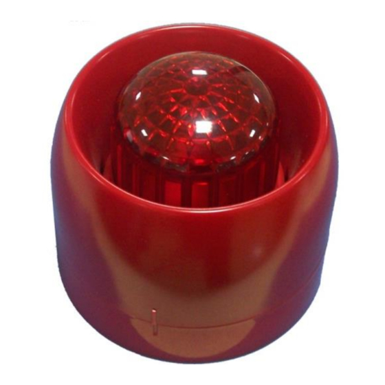
Acorn C-94DB Manual de inicio rápido
Navegue en línea o descargue pdf Manual de inicio rápido para Sistema de seguridad Acorn C-94DB. Acorn C-94DB 2 páginas. Conventional sounder strobe

Providing 2 tones.
Standard: EN 54-3.
Description
C-9403 Conventional Sounder Strobe is an audible
and visible alarm device used to warn people in field
when fire occurs. It can give audible and visible alarm
signal when applied to external 24VDC power (D1
connected with positive and D2 with negative).
A 25.5mm high shallow base and a 40mm high deep
base are available. Unless otherwise stated, all
descriptions in this manual take the shallow base as
example.
Connection & Cabling
Terminals on the base are shown in Fig. 2.
Tamper-proof
knockout
Drain Hole
110
?
Fig.1
G(10), D1(9), D2(7): Connecting with 24VDC power,
polarity-sensitive. G connects with positive output, D1
with
positive
input
and
Recommended Wiring
2
1.5mm
or above fire cable for 24VDC power line,
subject to local codes.
Installation
When surface mounted, the sounder strobe should
be placed 0.2m from the ceiling for normal space
height. When the conduit is embedded, the base
can be mounted on the back box. When the
conduit is surface mounted, the deep base should
be adopted. Knock the knockout hole, and connect
the conduit with it. The mounting hole spacing and
mounting direction are shown in Fig. 2. Mounting
method is shown in Fig. 3a and Fig. 4. The conduit
must be embedded when the shallow base is used,
as shown in Fig. 3b.
The base and the sounder strobe are twisted
together. When mounting, remove the sounder
strobe, thread cables through the cable entry in the
base and connect with corresponding terminals,
then twist the sounder strobe onto the base.
30309218
www.acornfiresecurity.com
Conventional Sounder Strobe
Arrow Upward
D2
with
negative.
www.acornfiresecurity.com
C-9403
Fig. 3a
Fig. 3b
Fig. 4
If the sounder strobe is required to be tamper-proof,
knock down the arch knockout as shown in Fig. 1
and fix it with ST2.9×6.5 self- tapping screws (in
this case, it can only be removed by a cross
screwdriver).
Application
Tone can set through pins inserted on the main circuit
board.
548e/01
2831-CPR-F0128
GST-0003-01
13
Issue 1.13
