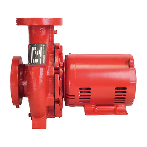
Armstrong 4280 Series Manual de instrucciones de instalación y funcionamiento - Página 5
Navegue en línea o descargue pdf Manual de instrucciones de instalación y funcionamiento para Bomba de agua Armstrong 4280 Series. Armstrong 4280 Series 10 páginas. Motor mounted pump
También para Armstrong 4280 Series: Instrucciones de instalación y funcionamiento (4 páginas), Instrucciones de servicio (4 páginas), Manual de instrucciones de instalación y funcionamiento (12 páginas)

limitations
See pump nameplate for speed, duty and maximum
pressure/temperature limitations. These limits must
not, under any circumstances, be exceeded without prior
consultation with Armstrong.
important:
Do not run the pump for any length of time under very
low flow conditions or with the discharge valve closed.
To do so could cause the water in the casing to
reach super heated steam conditions and will cause
premature failure and could cause serious and dramatic
damage to the pump and surrounding area.
installation
1.
location
• In open systems, locate the unit as close as practical to
the liquid being pumped, with a short, direct suction pipe.
Ensure adequate space is left above and around the unit
for operation, maintenance, service and inspection of
parts.
• In closed systems, where possible, the pumps should be
installed immediately downstream of the expansion tank/
make-up connection. This is the point of zero pressure
change and is necessary for effective pump operation. Do
not install more than one expansion tank connection into
any closed hydronic system.
• Electric motor driven pumps should not be located in
damp or dusty location without special protection.
• Airflow into the motor and/or motor fan should not be
obstructed.
2.
installation
• Recommended installation arrangements are:
2 .1
foundation
Mount the pump on a foundation sufficiently substantial to
absorb any vibration. A good foundation should weigh ap-
proximately 2.5 times the shipping weight of the pump.
Locate the pump on its foundation holes using the motor feet
as a template. Drill four holes of the required size and insert
the anchors.
Take the tamping tool (supplied with the anchors) and drive
home the lead sleeve until it is below the level of the founda-
tion and firmly fixed in the concrete.
Series 4280
motor mounted pump
Protruding bolts as shown at the left should be avoided since
this arrangement does not allow dismantling of the unit with-
out disturbing pipe connections.
2 . 2 levelling
Before installing the unit, use a straight edge to check that
the mounting surface is level. Place the unit on it's foundation
and insert shims under the motor feet to take up any irregu-
larities in the concrete. On flanged pumps, check the suction
and discharge flanges for horizontal or vertical position using
a straight edge and level. Tighten foundation bolts evenly.
2 .3 piping
Both the suction and discharge pipes should be indepen-
dently supported near the pump so that no strain is imposed
on the pump when the pipes are connected. All connecting
pipework should be accurately located – do not attempt to
force the suction and discharge pipes into position.
Suction Piping
Use short direct suction piping one or two times larger than
the pump suction nozzle. Arrange piping to eliminate poten-
tial air pockets and use an eccentric reducer to connect to the
suction nozzle. A strainer three or four times the area of the
suction pipe will prevent foreign materials entering the pump.
Discharge Piping
A check valve and gate valve should be installed in the
discharge line. If an increaser is used on the discharge side
to increase the size of the discharge pipe it should be placed
between the check valve and the pump.
3 .
pump piping - gener al
• Never connect a pump to piping, unless extra care is
taken to measure and align the piping flanges well.
Always start piping from pump. Use as few bends as
possible and preferably long radius elbows.
• Ensure the piping exerts no strain on the pump as this
could distort the casing causing breakage or early failure
due to pump misalignment.
• All connecting pipe flanges must be square to the
pipework and parallel to the pump flanges.
in sta l l a t io n &
o pera t ing instr uct io n s
5
