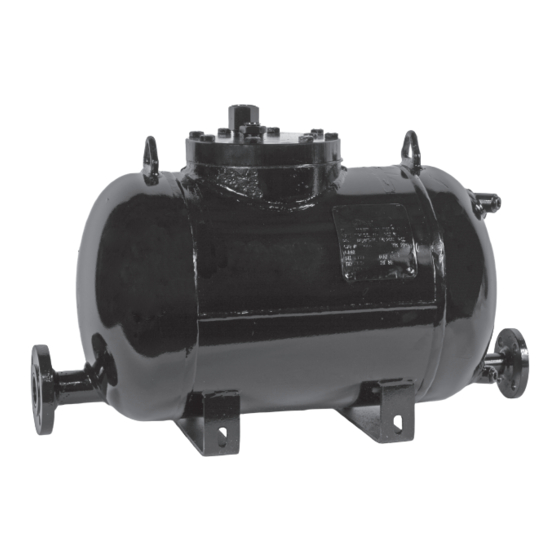
Armstrong Double Duty 6 Manual de instalación y mantenimiento - Página 2
Navegue en línea o descargue pdf Manual de instalación y mantenimiento para Bomba de agua Armstrong Double Duty 6. Armstrong Double Duty 6 6 páginas. Steam trap/pump combination

Features
1. The trap body has an integral pump to prevent flooding of the heat exchange equipment. It uses steam motive
with no electricity or special mechanical seals required.
2. The pump mechanism is attached to the cap which can be removed from the body without taking it out of the
condensate line, and the steam trap mechanism can be accessed through the cap opening.
Operation
Operating as a trap (system pressure greater than back pressure)
As the condensate flows through the inlet check valve, the trap and pump floats become buoyant and rise with the
fluid level. The upward movement of the float causes the trap valve to open. If the system pressure is greater than
the back pressure the condensate will flow through the steam trap valve into the condensate return.
Operating as a pump (system pressure less than or equal to back pressure)
If the system pressure is less than the back pressure liquid floods the body. When the condensate reaches the
upper trip point of the pump mechanism the motive inlet valve opens and the vent valve closes. The open motive
valve allows the motive fluid to enter and pressurize the body. The pressure inside the body shuts the inlet check
valve and when it is greater than the back pressure pushes the water through the discharge check valve into the
condensate return line. The float lowers with the water level and when it reaches the lower pump trip point the
motive inlet valve closes and the vent valve opens. This relieves the pressure in the body and allows it to fill again.
Installation
1. Filling head: Install the DD6 below the equipment being drained. Fill head is the distance from the top of the cap
to the bottom of the receiver. The standard fill head for the DD6 is 6 inches.
2. Liquid reservoir: Liquid flowing from the heat exchange equipment must be stored during the pump discharge
cycle. A liquid reservoir or receiver should be installed above the unit to prevent flooding the equipment
3. Vent piping: The vent pipe must be pitched to self drain. The vent connection is 1" npt.
4. Replace any temporary plastic plugs with appropriate fittings.
5. Gauge glass connections are ½" npt and 10" center to center.
Steam Main
Condensate Main
Strainer w/
Blowdown
IB Steam
Trap
Thermostatic
Air Vent
Vacuum
Thermostatic
Breaker
Air Vent
Equalizing
Line
Reservoir
Fill Head
Vacuum
Modulating
Breaker
Control Valve
Coil
2
Safety
Relief
Valve
Condensate Main
Alternate
Equalizing Line
High Pressure
Steam
D6469
