Armstrong Flex Flange Manual - Página 2
Navegue en línea o descargue pdf Manual para Unidad de control Armstrong Flex Flange. Armstrong Flex Flange 3 páginas.

1. Tighten bolts holding the Flex Flange and circulator flanges together by applying torque in equal amounts to
both flange bolts. Check pumps I&O for appropriate torque values.
WARNING: Ensure that Flex Flanges are installed with pump gaskets and that flange bolts are properly
tightened. Failure to follow these instructions will result in pump leakage, which may cause
property damage and/or personal injury.
2. Inspect connections for leaks after completing the installation.
OPERATION
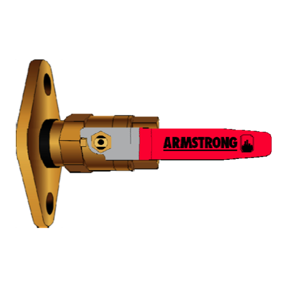
1. In the open position, the lever handle of the Flex Flange is perpendicular to the flange (as shown in Fig. 2).
2. To close the valve and isolate the pump from the system, turn the lever handle clockwise 90º. In the closed
position, the lever handle of the Flex Flange is parallel to the flange (as shown in Fig. 3).
Fig. 2 Flex Flange in OPEN position
Table 1.
Gasket information
1.390 ID x 2.203 OD
Size
x .250 thk
Astro Flanged
Use With
Circulators: 20, 25,
30, 50, 70 / S25
Included on Flex Flange sizes
0.5
Yes
0.75
Yes
1
Yes
1.25
NR
1.5
NR
1.828 ID x 2.187 OD
1.625 ID x 2.187 OD x
x .250 thk
.250 thk
E Series: E7, E8, E9,
E12, E14, E15, E17,
H51 , H52, H53,
H41
Yes
NR
Yes
NR
Yes
Yes
Yes
Yes
NR
Yes
Page 2 of 3
Fig. 3 Flex Flange in CLOSED position
2.187 ID x 2.562 OD x
.218 thk
E Series: E10, E11, E13,
E19, E21, E22, E23,
E24, H63, H 64, H65
NR
NR
Yes
Yes
Yes
