Armstrong Rada 50 Manual de instalación y mantenimiento - Página 7
Navegue en línea o descargue pdf Manual de instalación y mantenimiento para Unidad de control Armstrong Rada 50. Armstrong Rada 50 12 páginas. Water temperature controls, groups of fixtures, thermostatic

Commissioning the Rada 320
For Locked Temperature
1. Remove the temperature knob using a 3 mm hexagonal wrench (supplied).
2. Pull off the black polymer hub assembly which may inadvertently remain attached to the inside of the
temperature control handle. This is a "push fit" and can be "levered" out using a thin blade screwdriver or
pliers.
Figure 7-1
3. Rotate the spindle until required maximum blend temperature is obtained at outlet point (clockwise =
decrease temperature, counterclockwise = increase temperature).
When resistance is felt do not use force to turn any further, as this can damage the internal parts.
4. Once the desired maximum blend temperature is achieved, re-fit the hub without disturbing the spindle,
positioning it so that the center stop slot in the hub fits over the top of the cartridge stop (refer to Figure 7-1),
preventing any further rotation in either direction. Check that the blend temperature has not altered.
5. Refit the temperature knob. Make sure that the indicator points to 6 o'clock.
Rada 320 Servicing and Maintenance (Refer to Figures 8-1 and 8-2)
Rada 320 Thermostatic Mixing Valves should be inspected annually, or more frequently where acknowledged site
conditions such as high mineral content water dictate.
It is highly recommended that as a function of the annual inspection that the two "racetrack" shaped o-seals within
the valve are replaced (D33387) seal pack.
Rada 320 Thermostatic Mixing Valve is of non-serviceable single "cartridge construction". The cartridge can
be removed from the valve for inspection or replacement by first removing the chromed brass temperature
control handle using a 3 mm hex wrench. The black polymer hub assembly may inadvertently remain attached
to the inside of the temperature control handle. This is a "push fit" and can be "levered" out using a thin blade
screwdriver or pliers.
The chromed polymer Temperature Indicator Ring, which fits beneath the temperature control handle can be
"levered" off using a thin edged tool such as a razor blade knife.
Before proceeding further be sure to isolate the valve by turning off each inlet supply.
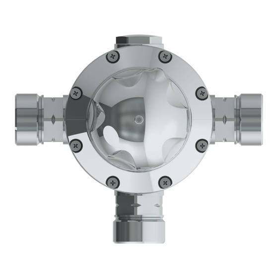
The complete cartridge assembly is accessed by first removing the 6 Phillips head-retaining screws and then
smoothly drawing the cartridge out. Do not twist or apply "side load" leverage when extracting the cartridge.
When installing a new or reinstalling an existing cartridge note the raised "H" on the hot inlet of the cartridge and
align to hot supply accordingly. Conversly, align raised "C" with cold supply.
7
