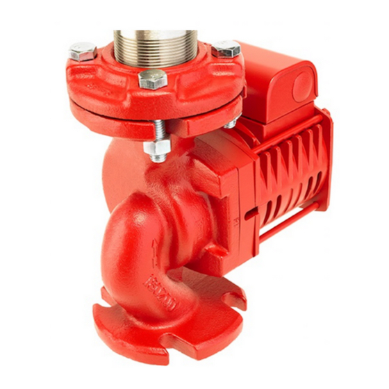
Armstrong E14.2 Manual de instrucciones de instalación y funcionamiento - Página 6
Navegue en línea o descargue pdf Manual de instrucciones de instalación y funcionamiento para Sistema de agua Armstrong E14.2. Armstrong E14.2 8 páginas. High efficiency circulator

i n s ta l l at i o n &
o p e r at i n g i n s t r u c t i o n s
6
5 .0 pump replacement in an existing
installation
5 .1 complete pump
1 Ensure that electric power is disconnected and locked out.
Loosen the screw from the terminal box cover and remove
the cover. Disconnect the supply wires from the circulator
only, leaving the capacitor wires connected.
All servicing personnel should be equipped with
proper personal protective equipment.
2 If valves have been installed, on the suction and discharge
sides of the pump, close them before attempting to remove
the circulator from the volute. If no valves have been installed
it may be necessary to drain the system.
Allow water to cool to 100°f (40°c) before draining
the system. It is best to leave the drain valve open
while working on the system.
3 To relieve any residual pressure which may be present in
the pump body, loosen the flange bolts and gently move
the pump body back and forth to allow the pressurized
water to escape.
note: Place a pan under the pump to collect the drain water.
4 If the entire volute is needed to be removed, then remove
the flange bolts and nuts. The entire circulator can then be
removed from the piping system.
5 Install the e. 2 series circulator where there will be sufficient
room for inspection and service. It is recommended that
isolation valves be installed on both the suction and
discharge sides of the circulator for future servicing. This
eliminates the need for draining the system when working
on the circulator (for example, when replacing the
mechanical seal).
6 Install suction and discharge flanges on the pipe ends. The
use of Teflon tape sealer or a high quality thread sealant is
recommended.
7 Pipe strain can be minimized by the use of pipe hangers
near the pump, positioned to support the suction and
discharge piping.
To wire the e. 2 series circulator, follow steps C through G in the
Electrical Wiring section above, noting that electrical supply
and grounding wires must be rated for at least 194°f (90°c).
5 . 2 motor end only
1 Turn off the pump leaving it installed in the line .
2 Ensure electrical power is disconnected and locked out .
3 Close the water supply at the points closest to the pump's
inlet and outlet .
E.2 Series high efficiency
circulator
4 For safety, allow water to cool to 100°f (40°c) before
draining the system. It is best to leave the drain valve open
while working on the system.
5 Bleed the water pressure from the pump.
6 Place a pan under the pump to collect the drain water.
7 While holding the motor body, loosen the four bolts that
attach the motor to the pump casing (volute). Start with the
two bottom bolts first and remove them, then slowly loosen
the top two bolts. Allow the water to drain from the bottom
of the pump. When the water has finished draining, remove
the two top bolts. Remove the motor straight out from the
volute being careful of its attached impeller. The motor is
heavy, do not drop it.
8 Install new casing gasket .
9 Install new motor end (with impeller and seal kit).
10 Tighten four motor end bolts in a crisscross pattern and
tighten evenly to 60 in/lbs.
11 Open isolation flanges or fill the system with water before
starting circulator.
12 To wire the e. 2 series circulator, follow steps C through G in
the Electrical Wiring section above, noting that electrical
supply and grounding wires must be rated for at least
194°f (90°c).
6.0 mechanical seal replacement
1 Follow steps 1 through 4 in section Existing pump removal
from system piping.
2 While holding the motor body, remove the bottom two
bolts that attach the motor to the pump casing (volute),
then slowly loosen the top two bolts. Allow the water to
drain from the bottom of the pump. When the water has
finished draining, remove the two top bolts. Remove the
motor straight out from the volute being careful of the
attached impeller.
Handle with care
The motor is heavy, and possibly hot,
do not drop it!
3 While holding the rotor very tightly by hand or a gloved hand
only, unscrew the impeller nut off the motor shaft by turning
it clockwise (i.e. opposite to most bolts and nuts). Place the
motor on its back, with the shaft up.
4 Remove the rotary part of the mechanical seal by gently
pulling it off the shaft. If it is too tight use two small flat
bladed screwdrivers to gently pry it off the shaft by placing
the flat side of the blades onto opposite sides of the
mechanical seal.
