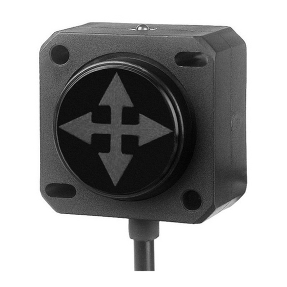
DIS Sensors QG40N Manual del usuario - Página 4
Navegue en línea o descargue pdf Manual del usuario para Interruptor DIS Sensors QG40N. DIS Sensors QG40N 5 páginas. Tilt/acceleration switch (sil1 plc)
También para DIS Sensors QG40N: Manual de usuario y seguridad (6 páginas), Manual del usuario (15 páginas)

QG40N Tilt SIL1 PLc
User Manual DIS-sensor
Signal processing
9
The signal processing consist of several aspect, addressed below.
9.1
Sample rate and averaging
The internal g-sensor chip is sampled every 10ms. Each sample of the element consists of 16 samples for each axis.
Resulting in sample rate of 1600 Hz. These samples are input for a 32 tabs FIR input low pass filter. Each 10ms new data is
available for the µC.
A decimating filter reduces the refresh rate by 4x, so refresh rate is 40ms
This decimating filter is averaging the values during the 40ms refresh rate (4 samples averaging)
9.2
Output filter:
The output of the sensor can be extra filtered by a 1
Via the optional 'QG40N configurator' a -3dB frequency or RC-time can be configured.
A longer low-pass filter time results is a smaller bandwidth and therefore a more stable output signal (less noise), but also
more phase delay.
9.3
Zeroing
To eliminate mechanical offsets a zeroing actions can be performed.
st
During the 1
minute after power up the zeroing input is sensitive for a zeroing action.
Sequence:
1.
Left input unconnected during power up for at least 0.5s
2.
Switched/connect input to Gnd for at least 0.5s
3.
Left unconnected again
4.
Result: The sensor will set the current inclination position as 0°. The actual zeroing point is where the input changes
from Gnd to unconnected.
The maximum zeroing-range is specified in the datasheet. Horizontal mounting sensors have zeroing-range-limit of ±5°,
vertical mounting sensor can be zero-ed over full 360°.
The new 0° value will be stored in non-volatile memory (EEPROM)
9.4
Delay times
Each switching output is preprogrammed to have certain on/off delays. See datasheet for details
These delays can be tuned by the customer (optional QG40N configurator)
10 Internal diagnostic tests
To ensure safety the hard- and software of the safety sensor is continue checked to a certain extend (Diagnostic Coverage) .
When a failure is detected both outputs will switch to non-conducting. Non-conducting should lead to 'low' thanks to
external pull down resistor. Customer shall consider this situation as 'unsafe' and take appropriate actions to bring the
application to 'safe-state'
11 Document revision control
v0.1 Draft by MvA
v1.0 After review by RM
v1.1 Chapter 4: PLd corrected to PLc
v1.2 20200225 Available measuring ranges updated,
V1.2
st
order low-pass filter. Default this output filter is disabled.
4
page 4 of 5
