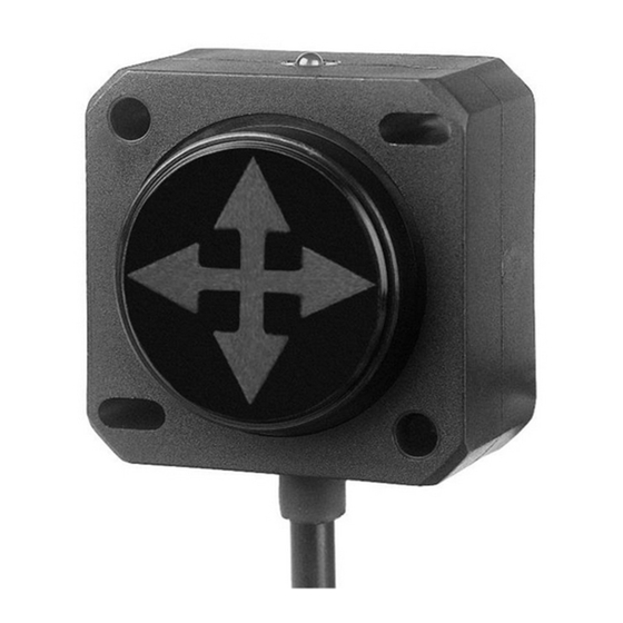
DIS Sensors QG40N Manual del usuario - Página 7
Navegue en línea o descargue pdf Manual del usuario para Interruptor DIS Sensors QG40N. DIS Sensors QG40N 15 páginas. Tilt/acceleration switch (sil1 plc)
También para DIS Sensors QG40N: Manual del usuario (5 páginas), Manual de usuario y seguridad (6 páginas)

Safety Level
SIL safety level: SIL CL1 (claim limit 1 according to IEC 62061)
PL safety level: PLc (according to EN ISO 13849)
Architecture: HFT=0 (according to IEC 62061) & CAT2 (according to EN ISO 13849)
This is a self-certified safety device.
The firmware of this device is developed according to EN ISO 13849 and meets the SRESW
requirements for both 'PL a to d' and 'PL c or d'.
See separate 'Declaration of Conformity' for all safety related parameters.
Internal Diagnostic Checks
Comprehensive safety checks are performed during both the start-up and operational phases. In case
of any diagnostic errors, both sensor outputs are forcefully switched to a "non-conducting" state in a
permanent manner to inform the application that an unsafe situation could occur.
4.3.1
MCU EEPROM Error
MCU EEPROM error check involves verifying the integrity of the EEPROM data. The microcontroller's
firmware calculates a checksum or uses a cyclic redundancy check (CRC) algorithm on the stored
data. This computed value is then compared with a pre-determined reference value. If they match, it
indicates that the EEPROM data is valid; if not, an error is detected. This process ensures that data
stored in the EEPROM remains accurate and uncorrupted.
4.3.2
MEMS Self-test Error
The MCU briefly activates the MEMS acceleration chip's self-test mode to verify its proper
functionality
4.3.3
Output Error
As a component of the required Diagnostic Coverage for achieving SIL1 functional safety, it is
necessary to monitor the switching output of the sensor. To facilitate this, the SIL1 tilt switch
incorporates a feedback mechanism from its output to the microcontroller. If the logical feedback
deviates from expected parameters, the sensor transitions into a permanent critical state until a
system reboot is performed. It is crucial to ensure the correct operation of the sensor that no voltage
is applied to the NPN or PNP outputs.
4.3.4
MCU Errors
The MCU is a key component that manages the sensor's operation, data processing, communication,
and other functions. Therefore we continuously monitor error or fault that occurs within the MCU.
•
Unknown interrupt
An MCU might not handle interrupts correctly, leading to missed sensor events or incorrect
responses to interrupts.
RAM error
•
DIS SENSORS BV
User Manual - QG40N Tilt/Acceleration Switch (SIL1 PLc) V2.0
6
