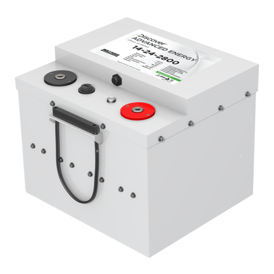
DISCOVER 14-24-2800 Manual de instrucciones - Página 11
Navegue en línea o descargue pdf Manual de instrucciones para Accesorios para cámaras DISCOVER 14-24-2800. DISCOVER 14-24-2800 13 páginas. For motive power applications
También para DISCOVER 14-24-2800: Manual de instrucciones (14 páginas)

11. 14-24-2800 TECHNICAL SPECIFICATIONS
Electrical Specifications
Nominal Voltage
Charge Voltage
Maximum Voltage
Minimum Voltage
Nominal Capacity
Nominal Energy
Max Continuous Charge Current
Max Continuous Discharge Current
Fuse
Cell Chemistry
Cell Modules
Self-Discharge 25°C / 77°F
Fault Limits
Over Temperature - Discharge Protection
Over Temperature - Charge Protection
Low Temperature - Discharge Protection
Low Temperature - Charge Protection < -20°C/-4°F for 120s
Over Voltage Protection
Under Voltage Protection
Over Current Protection
Mechanical Specifications
Battery Dimensions (HxWxD)
Battery Weight
Shipping Dimensions (HxWxD)
Shipping Weight
Terminal
Terminal Hardware
Terminal Torque
Case Material
Enclosure IP Rating
Charge Temperature Range
Discharge Temperature Range
Storage Temperature Range
25.6 V
27.2 V
29.2 V
20 V
110 Ah
2816 Wh
110 Adc
110 Adc
150 A Internal Fuse.
Provides backup over-
current protection
LiFePO
4
8S 22P
< 3% per month (battery
off)
> 60°C/140°F for 120s
> 60°C/140°F for 120s
< -20°C/-4°F for 120s
> 3.7 V in any cell module
for 60s
< 2.5 V in any cell module
for 5s
> 150 Adc
276 x 347.5 x 329.5 mm
40 kg
470 x 430 x 390 mm
48.4 kg
M8
M8 Stainless Steel Bolt,
Flat Washer, Lock Washer
(Supplied)
9.0 Nm +/- 3
Powder Coated Cold
Rolled Steel
IP 55
0°C/45°C (32°F/113°F)
-20°C/50°C (-4°F/122°F)
-20°C/45°C (-4°F/113°F)
Operational Specifications
Battery Management System (BMS)
Cell Balancing
Non-Volatile Memory
Lifetime Logged Data
Communication Ports
Communication Connector
Circular 12 PIN
Regulatory Approvals
Integrated, with Solid State
Relay (SSR)
Passive balancing when
Cell Voltage > 3.35 V
Yes
• Time
• High/low average cell
module voltage
• Balancing, Fault and
Relay State
• Battery SOC, Current,
Voltage, Temperature
• Charge Energy In/Out
• Isolated USB
• Isolated CAN (AEBus)
USB Type A Female
Circular 12 Pin
Pin 3
AEBus CAN GND
Pin 4
AEBus CAN High
Pin 5
AEBus CAN Low
Pin 6
LED GND
Pin 7
LED +5V
Pin 8
Key/Reset +
Pin 9
Key/Reset -
Pin 11
AEBus CAN +5V
UN 38.3, IEC 62133,
UL 2271, UL 1973
11
