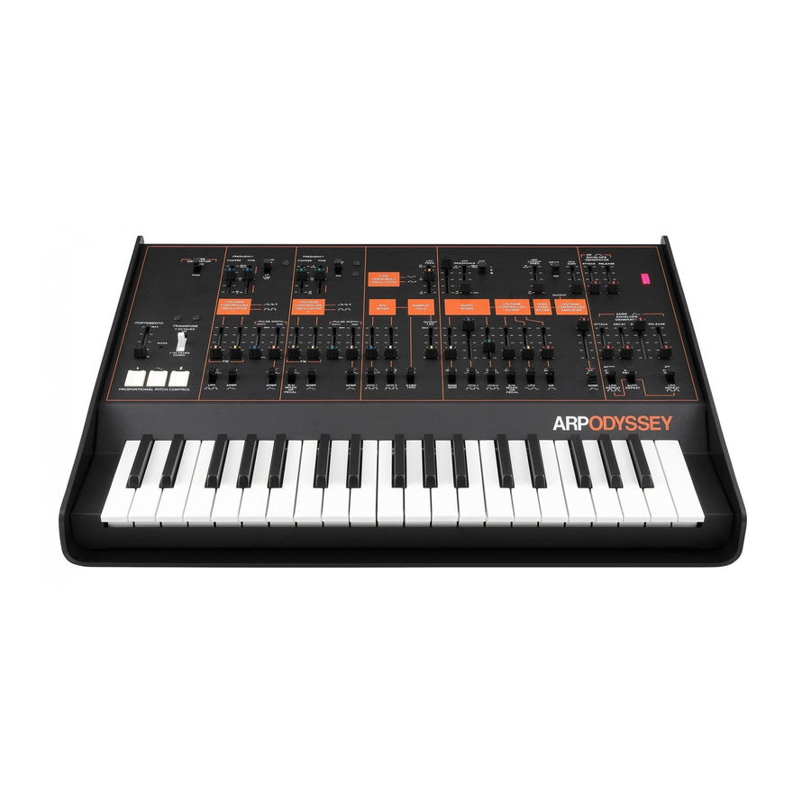
ARP ODYSSEY Manual - Página 9
Navegue en línea o descargue pdf Manual para Sintetizador ARP ODYSSEY. ARP ODYSSEY 18 páginas. Electronic music synthesizer
También para ARP ODYSSEY: Manual del usuario (18 páginas)

from the back of the Odyssey, the same
switch position selects control by the output
of the 5/H mixer.
12. The
sample
and
hold
circuit
js
a control-
ler;
it
is used only to control VCO 1, VCO 2,
and/or
the
VCF.
In
order
to
hear what it does
listen
first
to
VCO 2 as you have done before
and then experiment with the controls indi-
cated in
Figure T.
By "sampling" at a given
instant
the signal
voltage from the
S/H
mixer, the sample and
hold circuit produces a series of
voltage levels.
If
these in turn are used to control a VCO, the
result
is a series of
pitches. The
switch under
the sample and hold circuit selects either the
LFO
or the keyboard as a triggering source.
If
the
keyboard
is
selected (
Figure
U ) , then a
new sample will be
taken
every
time
you press
a key; if
the L FO
is selected, then new samples
will be taken at regular intervals corresponding
to the
frequency setting of
the L FO.
When
the
signal sampled is primarily noise,
the output voltage
levels
will be
random
and
so of course will be the pitches produced
from
VCO 2 ; but if the signals being sampled are
Page 14 ARP ODYSSEY
Sample
&
hold
Figure T
AUDIO
~••~'-'-"!FINE
ii
'°"'
t
Cl
j
r•uLSE
wroTH
7
I
ouTPur
J_ J_
:( : :
~t
: ~
1-
~
- I ~ .
i
~
i
i
--
i-
. . .
~
...
~
J_ J_
J_
Figure
U
LFO
S/H
LFO
VC0·1
NOISE
LFO
IV\,
fVv
"""
GEN
TRIG
f;1
a.
J;l
B
I! I!
vro-1
ftYBO
_J1.J"\
~
.I"-...
.fUL
.fUL
TAIG
AUDIO
ICYBD
SYNC
l
:,;;t·
I
@ 1-?··t
e
zgg
OFF
100
'
"'
.
-
-
,;
..
I
_
-::
I
VOLT~GE
CONTROLLED
OSCILLATOR
.IV'\
1
1 l
r
Pulse w10TH
7
f
f
r
PULSE
w 10TH 7
111111r-~
L..:::. ...
..=-i
l_
t..=.,
..
_:__j
J_
LFO
LFO
S/H
LFO
VCQ-.1
NOISE
LFO
fVv
/\/\.
I\/\,
r-...J--.1-
GEN
TRIG
B
I!
B 8
LFO
FREQ
. .
_I
·1
OUTPUT
. . . I : ~
""ILAG
-
-
- -
-
-
,
MIH
l,IIH
l_
l_
LFO
TRIG
e
J;1
~r
~
AOSR
VC0-1
VC0-2
t-'l'BO
•
.r-,._
Ml ~ :R
_t--,.._
..J'-.....
J"U'1...
.J'l.I'L
TRIG
PEDAL
Figure V
See Patch 10 for a thorough sample and hold
patch.
Figure
W
regular
and periodic (any combination of the
VCO
1
and VCO 2 signals), then the output
from
the
sample and
hold
circuit will
tend
to
be a
repeating
pattern also.
It
may
·
be an ex"
tremely complex one, or
it
may be extremely
simple
.
For
an example
of
a simple one,
switch VCO
1 to its low
freq
range
and feed
the
VCO
1
sawtooth into
the
S/H mixer. Use
the sample and hold output to
control VCO 2
and
listen to
VCO 2
through
the audio mixer.
Set
the LFO
freq
to
about halfway up, and
the
VCO 1 freq
at
about 2 Hz.
You should
hear a
descen.
d ing "staircase" of pitches, like a
scale passage or an arpeggio (Figure
V ). Speed
up
VCO
1
freq and hear the
repeating
patterns.
The output lag slider
(Figure W )
"smootbes
out" sudde.n changes of voltage from
the
sample and hold circuit.
With the
same patch
you have been listening
to,
move the slider
slowly from "min" to "max" and back again.
13.
The. keyboard is
a controller.
By con-
trolling
the pitch of the VCO's and providing
triggering signals
to
the envelope generators, it
allows you
to
play your Odyssey as though it
were a standard keyboard instrument.
The
More sample
&
hold
ARP ODYSSEY Page 15
