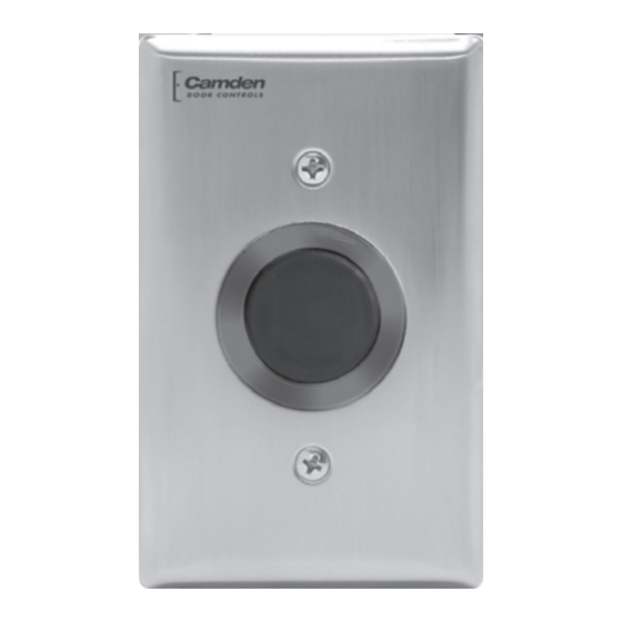
CAMDEN SureWave CM-332 Series Manual de instrucciones de instalación - Página 3
Navegue en línea o descargue pdf Manual de instrucciones de instalación para Interruptor CAMDEN SureWave CM-332 Series. CAMDEN SureWave CM-332 Series 8 páginas. Active infrared "hands-free" switches

CM-331 & CM-332 Active Infrared "Hands-Free" Switches Installation Instructions
CAUTION:
Do not apply power to the unit until all secondary wiring is
complete, and dip switches have been set.
Power – TB1
Camden CM-331/332 Sure-Wave switches can be powered
from 12 or 24 Volts, AC or DC. Connect power to pins 1&2
on the TB1. This is a non-polarized connection.
Inputs
Camden Sure-Wave switches provide inputs for Door
Contacts, Request to Exit and remote control of the LED
Light ring. These inputs are found on TB2. All inputs require
a dry contact closure to operate.
TB2 Inputs
Pin
Function
Description
Number
1
Request to Exit
A dry contact closure across these
inputs will activate the relay(s) as per
their settings.
2
Request to Exit
3
Door Contact
Normally closed, Used for Security
Mode
4
Door Contact
5
Remote LED
External light ring control. A closed dry
contact on this input will toggle the
light ring color.
6
Remote LED
Outputs
The Sure-Wave switches provide Form 'C' relay outputs. The
CM-331 has 1 Form 'C' output and the CM-332 has 2 Form
'C' outputs. Selecting the correct output is also dependant
on the operating mode chosen. Most applications will
utilize the N.O. and Common terminals.
Relay 1 Output (TB3)
1
Normally Closed
2
Common
3
Normally Open
Relay 2 Output (TB4), (CM-332)
1
Normally Closed
2
Common
3
Normally Open
Section 3: Applications & Set-up
Applications
DIP 1
LED Enable
Audio Enable
Fail Safe
EXT
Sounder
Error/Alarm
LED
POT 1
Range
Adj.
CM-331
Range Sequence
DIP 1 – Options Switch
SW1 – LED Enable
When SW1 is ON, the green LED will illuminate when the
switch is activated. When SW 1 is OFF (default), the green
LED will remain off.
SW2 – Audio Enable
When SW2 is ON, an audible beep is generated when the
switch is activated. When SW2 is OFF (default), no audible
beep is generated.
SW3 – Fail Safe/Fail Secure
This option changes the state of the relays on the Sure-Wave
switches. When SW3 is ON, the relay outputs are switched.
NO becomes NC and NC becomes NO. SW3 is OFF by
default.
SW4 – External LED Control
The LED light ring can be controlled externally by providing
a contact closure on the REM input (pins 5&6) on TB2.
When SW4 is ON, a contact closure across the REM input
will change the light ring color from its idle to active colors.
When SW4 is OFF, the light ring colors change with the state
of the switch.
Page 3 of 8
DIP 2
Motion Sensing
Modes
Relay Operation
Modes
J 1
Activate
LED
POT 2
Relay
OP Time
DIP 1
DIP 2
LED Enable
Audio Enable
Fail Safe
EXT
Sounder
Error/Alarm
LED
POT 3
Delay Adj.
POT 1
Range Adj.
CM-332
Motion Sensing
Modes
Relay Operation
Modes
J 1
Relay
LED
POT 2
Relay 1
OP Time
POT 4
Relay 2
OP Time
