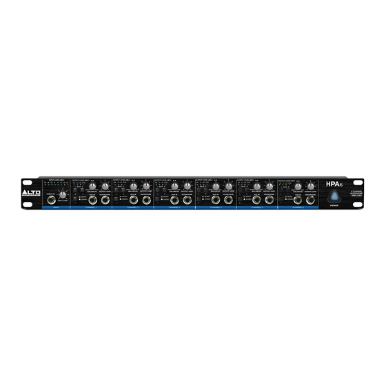
Alto HPA6 Manual del usuario - Página 6
Navegue en línea o descargue pdf Manual del usuario para Amplificador Alto HPA6. Alto HPA6 13 páginas. 6-channel headphone amplifier
También para Alto HPA6: Manual del usuario (14 páginas), Manual del usuario (14 páginas)

3.1 The ront anel
F
P
1.Direct In Input: The Direct In Input is used to feed the signals coming from an external source. While
using the Direct In Input, the Main signal applied on the rear panel is interrupted automatically.
2.Input Gain Control: This control sets the input signal level coming from Main/Direct In.
3.Input Level Meter: This 8-digit Input Level Meter informs you about the input signal level within a
range from -24dBu to +18dBu.
4.Aux In Input: The Aux In Input is used to feed the further input signal, which can be mixed with the Main/
Direct In signal via Balanced Control.
5.L Mute Switch: This push-button mutes the Left input signal.
6.R Mute Switch: This push-button mutes the Right input signal.
7.Mode Switch: This push-button switches the operational mode between Mono and Stereo. Press this
button for Mono application, and the Mono LED (8) lights up.
8.Mono LED: This LED informs you the current operational mode. Press the Mode Switch(7) for Mono
application, this LED lights up.
9.Headphone Out Output: This 1/4" TRS phone jack is connected in parallel to the rear panel output
connectors, and provides an additional option to monitor the individual channels. When this unit is pe-
rmanently installed in rack, this proves to be a useful function.
10.Balanced Control: This control sets the proportion between the Main/Direct In signal and the input signal
applied to Aux In Input.
11.Output Gain Control: This control sets the volume of the individual channels and refers to both the
Left & Right Channel and the Headphone Out.
12.Output Level Meter: This 4-digit Output Level Meter informs you about the output signal level within
a range from 24dBu to +12dBu. If the Clip LED lights up, you should turn down the Input Gain Control
or/and the individual Output Gain Control (only for the Channel incurs Clip) to avoid any distortion.
3.2 The Rear Panel
110-120V
AC INPUT
AC INPUT
95-120V
95-120V
60Hz
60Hz
220-240V
/210-240V
/210-240V
50Hz
50Hz
TIP:L- CHANNEL
Rated Power
Rated Power
RING:R- CHANNEL
Consumption 40W
MIN. LOAD 100OHMS
FUSE:
210-240V: T160mAL 250VAC
210-240V: T160mAL 250VAC
95-120V: 315mA 250VAC
95-120V: 315mA 250VAC
REPLACE FUSE WITH
REPLACE FUSE WITH
CORRECT TYPE ONLY
CORRECT TYPE ONLY
13
14
INPUT LEVEL(dBu)
24
18
12
R
LTO
DIRECT IN
MAIN SECTION
1
HEADPHONE OUT 6 HEADPHONE OUT 5
HEADPHONE OUT 6
HEADPHONE OUT 5 HEADPHONE OUT 4 HEADPHONE OUT 3 HEADPHONE OUT 2 HEADPHONE OUT 1
22
21
20
19
5
6
10
3
12
OUTPUT LEVEL(dBu)
6
0
6
12
18
24
0
12 CLIP
L
MUTE R
3
2
4
MAIN IN
BALANCED
AUX IN
1
5
MONO
6
0
STEREO
INPUT GAIN
CHANNEL 1
2
8
7
4
TIP/PIN 2
RING/PIN 3
SLEEVE/PIN 1
MAIN OUTPUT RIGHT
18
17
5
11
3
2
4
1
5
0
6
AUX
OUTPUT GAIN
HEADPHONE OUT
9
TIP/PIN 2
TIP/PIN 2
RING/PIN 3
RING/PIN 3
SLEEVE/PIN 1
SLEEVE/PIN 1
MAIN OUTPUT LEFT
MAIN INPUT RIGHT
16
PUSH
PUSH
TIP/PIN 2
RING/PIN 3
SLEEVE/PIN 1
NEW
TIDE
NEW
TIDE
3
3
2
1
2
1
MAIN INPUT LEFT
15
