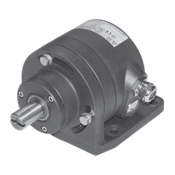
Camille Bauer KINAX WT 717 Manual de instrucciones - Página 16
Navegue en línea o descargue pdf Manual de instrucciones para Transmisor Camille Bauer KINAX WT 717. Camille Bauer KINAX WT 717 20 páginas. Transmitter for angular rotation

8. Electrical connections
Screw terminals and cable glands are provided for making
the electrical connections to the transmitter.
Note that, ...
... the data required to carry out the prescribed
measurement must correspond to those mar-
ked on the nameplate of the KINAX WT 717
(measuring) input, measuring output, power
supply)!
... the total loop resistance connected to the output
(receiver plus leads) does not exceed the maxi-
mum permissible value R
output", section "5. Technical data"!
... twisted cores must be use for the measured
variable input and output leads and routed as
far away as possible from power cables!
In all other respects, observe all local regulations
when selecting the type of electrical cable and
installing them!
In the case of "Intrinsically safe" explosion-
proof versions, the supplementary information
given on the EC-Type-Examination Certifi cate,
the EN 60 079-14 and also local regulations
applicable to electrical installations in explosion
hazard areas must be taken into account!
Type: WT717-1100 0000 000
!
Ord.: 000/000000/000/000
0.5
Supply
Voltage
12...33V DC
Camille Bauer AG, CH-5610 Wohlen, Switzerland
Fig. 5. Example of a nameplate.
8.1 Connecting transmitter
To connect the transmitter, fi rst remove the 3 screws (3.2),
and remove the cover (3.1). The maximum wire gauge the
terminals (4.1) can accept is 1.5 mm
Fig. 6. Rear (3) with terminals (4.1) and cable glands (4).
Left:
with cover (3.1) closed.
Right:
without cover (3.1).
16
! See "Measuring
ext.
Range:
0...50º
linear
Output:
2-wire, 4...20mA
Rotation Sense:
2
.
(5.1)
(3.2)
(3)
(4.1)
(3.1)
(4.2)
(4)
Undo the gland nut and remove the pinch ring and seal from
the gland opening. Place these parts over the cable in the
correct order and pass the end of the cable through the gland
hole into the rear of the transmitter.
Strip the insulation from a suitable length of the leads and
connect them to the terminals (4.1) according to Fig. 7.
Then fi t the gland seal, pinch ring and nut. Tighten the gland
nut and replace the cover.
–
+
– +
H
Fig. 7. Connection diagram.
9. Fine adjustment
The analog output can be fi nely adjusted using the 2W2
confi guration software. Select the menu item "Adjustment"
under "SERVICE". In the "Analog output" window, the zero
position and the end value can now be adjusted.
Procedure:
1. Put the transmitter into operation and connect the pro-
gramming device according to Fig. 5 (AUX switch on the
PK 610 on the OFF position).
(5)
2. Place the measuring device in the zero position, i.e. in the
position in which the KINAX WT 717 should output 4 mA.
Adjust with the "ZERO" virtual knob until the output is
correct.
3. Place the measuring object in the end position, i.e. in the
position, in which the KINAX WT 717 should output 20 mA.
Adjust with the virtual knob "Span" until the output signal
is correct.
4. Close the adjustment with the "Done" button.
The adjusting range of the zero position and span is 5%.
If this range is not suffi cient, the span can be adapted by
changing the mechanical characteristics (increase/decrease
the measuring span).
If required, the direction of rotation can be reversed using
the confi guration software.
H = DC power supply
H = 12...33 V
resp. H = 12...30 V
with Ex version
R
= External resistance
ext
R
ext
