EDI LMD Series Manual de instrucciones - Página 4
Navegue en línea o descargue pdf Manual de instrucciones para Sensores de seguridad EDI LMD Series. EDI LMD Series 15 páginas. Deflectometer, inductive loop monitor
También para EDI LMD Series: Manual de instrucciones (15 páginas)

1.1 DESCRIPTION
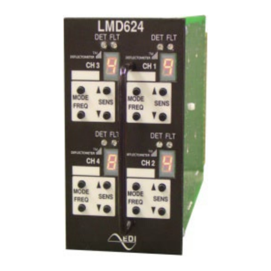
The LMD602 two channel and LMD604 four channel Nema TS-1 rack mounted inductive
Loop Monitor with DEFLECTOMETER® Series is built on the international card format with
double-sided 44 pin edge connectors for connection of power, loop inputs and call outputs.
The units meet or exceed all requirements for detectors as defined in Nema Standard
TS1-1989 (R2005). Each channel has individual controls for setting up sensitivity,
operational mode and frequency on the front panel. Two high intensity front panel LEDs
indicate vehicle detection, timing operation and fault monitoring status for each channel.
Call outputs are available in either relay or optically-isolated solid-state transistor form.
Model
Channels
LMD602
Two Channel
LMD602-R
Two Channel
LMD602T
Two Channel
LMD602T-R
Two Channel
LMD604
Four Channel
LMD604T
Four Channel
1.2 OVERVIEW
A dynamic Overview of the LMD operation which includes an LMD Simulator is available on
the EDI Web Site; www.EDItraffic.com.
1.3 DEFLECTOMETER® FEATURE
The LMD Series Loop Monitor introduces a concept to the inductive loop detector field that
revolutionizes the process of installing and programming a loop detector. The new user
interface of the LMD Series provides the feedback necessary to the signal technician to
quickly and accurately program the parameters of the detector exactly to the loop plus lead-
in system characteristics.
The DEFLECTOMETER display shows the relative strength of the call while a
vehicle is in the detection zone. This provides feedback that the unit is
optimally tuned to detect vehicles of all sizes.
Setting the sensitivity level of the detector can be easily done in one step with
a "typical" vehicle parked in the detection zone. The DEFLECTOMETER
display updates dynamically as the sensitivity level is changed. See section
2.1.1.
The simple push-button interface is intuitive and eliminates many of the
reliability problems found with tiny DIP switches of conventional detectors.
Operational mode, Frequency, and Sensitivity are all programmed and
displayed using the push-button interface. Settings are stored in non-volatile
memory.
Loop diagnostic capabilities incorporated within the LMD Series Loop Monitor enable the
detection of short or open circuit loops and sudden changes of inductance exceeding 25
Eberle Design Inc.
LMD602 and LMD604 Series
Operations Manual
Section 1
GENERAL
Features
Relay Outputs
Delay and Extension Timing
Delay and Extension Timing, Relay Outputs
Delay and Extension Timing
Why guess when you can know!
Page 1
