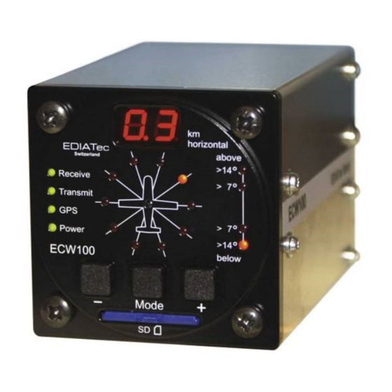
EDIATec ECW100 Manual de instalación - Página 6
Navegue en línea o descargue pdf Manual de instalación para GPS EDIATec ECW100. EDIATec ECW100 14 páginas. Collision warning unit
También para EDIATec ECW100: Manual de instrucciones (15 páginas)

7. Power/Data
The cable kid with a D-Sub-15 connector "power/data" is to lock in place. The key to the
connections is defined by the numbers on the connector:
Pin
Color
1
red
2
3
4
5
black
6
7
8
9
10
11
12
13
14
15
The cable kit contains at minimum two cables for power (Pin 1 and 5).
In spite of reverse polarity protection, it is important to check for correct polarity during
installation; in particular the power supply and data wires must not be interchanged.
Power/Data
+8 .. +26 V DC
+8 .. +26 V DC
GPS test
Ground
Ground
GPS test
GPS test
GPS test
+3 V DC
nc
RX
TX
Ground
Aux Line Intercom
Ground
Remarks
Power line
(Pin 1 and 2, Pin 4 and 5 are wired together
inside)
Power to the external display
Serial data RS-232 available for use in other
systems e.g. external display, PDA, TR-DVS...
(NMEA data: GPS, warnings)
Driver for intercom or head set
Page 6
