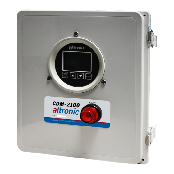
Altronic CDM-2100 Manual de instrucciones - Página 6
Navegue en línea o descargue pdf Manual de instrucciones para Instrumentos de medida Altronic CDM-2100. Altronic CDM-2100 20 páginas. Differential pressure monitor

Press ENTER again to change the cursor to the é icon. Use the UP and DOWN
arrow buttons to make the desired setpoint changes. The procedure is repeated
to change the first setpoint value.
8.2 HYSTERESIS
Hysteresis can be used when the output switch is configured as non-latching
to prevent the output switch from oscillating or turning on and off around the
setpoint. The hysteresis is implemented as a time, in seconds, that begins
when the sensor input value returns to within the setpoint value limits. When
the input value returns to within the setpoint value limits, the hysteresis timer
starts and the switch stays tripped for the configured hysteresis time. If during
the hysteresis time the setpoint is violated again, the hysteresis timer starts
over. The hysteresis value can be set from 0 to 99 seconds. To set the hysteresis
value, point to HYST and press the ENTER key. Use or to increase or
decrease the hysteresis time and press ENTER to save the new value.
CHANNEL 1
HI
LO
~HYST.
PREVIOUS MENU
8.3
SETPOINTS
The SETPOINTS menu allows the user to set a setpoint value for Low and
High, and set the hysteresis value for each channel.
REFER TO SECTION 8 FOR DETAILS ON SETPOINTS
8.4
CALIBRATE
The gauge is calibrated at the factory and should not require additional
calibration. However, calibration can be performed in the field many times
over the life of the gauge. Each channel is calibrated separately to the type of
input transducer selected. The calibration mode is used to calibrate the zero
and span values. Calibration can be performed from the front keypad without
disassembling the gauge. A calibrator or simulator capable of outputting the
correct signal for the type of transducer selected for that channel is required
to provide a calibration reference.
CALIBRATE:
~FULL CAL
TWEAK LO ONLY
TWEAK HI ONLY
RECALL FACT CAL
PREVIOUS MENU
8.4.1
CALIBRATION PROCEDURE
Connect the appropriate calibrator or simulator (for thermocouples use the
proper type of thermocouple extension wire) to the gauge for channel 1 or 2,
follow the hook-up drawing for that sensor type. Be sure that the sensor type
and the engineering units of the calibrator match the type and engineering
units of the instrument before performing a calibration.
CDM-2100 OM 3-21
All rights reserved © ALTRONIC, LLC 2021
6in H2O
0in H2O
9 SEC.
CHANNEL 1
NOTE: During calibration, the unit
allows 2 minutes between keystrokes
to change or save a new calibration.
If 2 minutes lapse without a keystroke,
the device will automatically return
to the home screen with the previous
values. The new calibration information
is saved only if the ENTER key is
pressed and the display reads SAVED.
6
