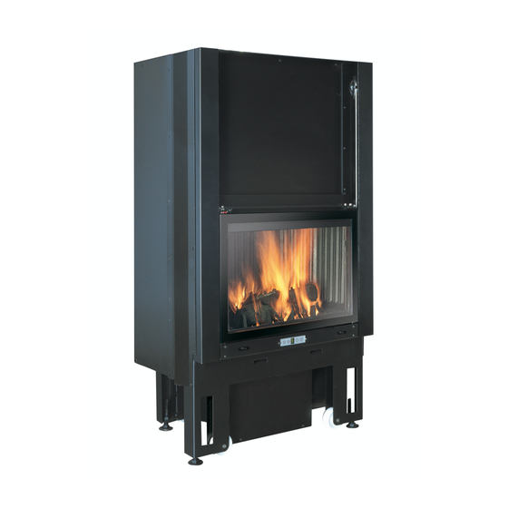
EdilKamin FORTE UP2 Manual de instalación, uso y mantenimiento - Página 5
Navegue en línea o descargue pdf Manual de instalación, uso y mantenimiento para Estufa de leña EdilKamin FORTE UP2. EdilKamin FORTE UP2 16 páginas.

INSTALLATION INSTRUCTIONS
Important warnings
As well as that indicated in the pre-
sent document, bear in mind the UNI
rules:
- n. 10683 - wood heat generators:
installation requirements
- n. 9615/90 - calculation of the
chimney internal dimensions.
In particular:
- before starting any mounting opera-
tion, it is important to verify the
compatibility of the plant as establi-
shed by the UNI 10683 rule in para-
graphs 4.1/ 4.1.1 / 4.1.2.
- once mounted, once mounted, the
installer must "start up" the plant and
issue the documentation requested in
the UNI 10683 rule, respectively in
paragraphs 4.6 and 5.
Before installing the cover, verify the
correct functioning of the connections,
the controls and all moving parts.
The verification must be carried out
with the chimney having been on for a
few hours, before covering the hearth,
in order to eventually intervene.
Therefore, the finishing operations
such as for example:
- manufacture of the false hood
- mounting of covering
- carrying out stripping, painting, etc.
must be carried out once tested with
positive result.
Therefore, Edilkamin does not
answer for burdens deriving from
both demolition and reconstruction
interventions, even if subsequent to
replacing hearth pieces which resul-
ted faulty.
Calibration and start up to be carried
out by the dealer.
Vorwort
• The FORTE UP2 hearths must be
installed keeping to the following
instructions, as the safety and plant
efficiency depend on the correct
installation.
• Carefully read the present instruc-
tions before mounting.
• EDILKAMIN declines any responsi-
bility for eventual damages deriving
from the non compliance with the pre-
sent instructions and, in case, any war-
ranty right will be void.
• The FORTE UP2 hearth is supplied
already assembled on non returnable
pallet. The inside covering of the
hearth is supplied already installed.
• A model identification label is
applied under the hearth hatch; the
label can be seen until the hearth is
covered. The model identification
number is indicated in the documenta-
tion supplied with the product.
Building protection
All the building surfaces near the
hearth must be protected against over-
heating. The insulating measures to be
adopted depend on the type of surfaces
present and how they are made.
Hot air outlets / Grillsr
The hot air outlets must be placed at a
minimum distance of 50 cm from the
ceiling and 30 cm from the furniture.
Position the grills or the air outlets at
the highest point of the covering, in
order to avoid heat accumulating insi-
de the same covering. Position the
grills or the air outlets so that they can
be easily accessed for cleaning.
Heating insulation
The insulating layers must not have
joints and have to be overlapped. The
thickness of the insulating material
must be of at least 3 cm.
Ornamental beams
The realisation of eventual wood orna-
mental beams in front of the hearth
covering is allowed only if they are
outside the radiation field, at a distan-
ce of at least 1 cm from the same cove-
ring. The air space which isolates the
ornamental elements and the covering
must be such not to accumulate heat.
The wood ornamental beams cannot
be integrating parts of the building.
15
Floor opposite the hearth
Floors made with fuelling materials
must be protected by a sufficiently
thick, non fuelling cover.
The floor protection must be equal to:
frontally:
- the corresponding height of the fire
surface from the floor plus 30 cm and,
in any case, min. 50 cm
laterally:
- the corresponding height of the fire
surface from the floor plus 20 cm and,
in any case, min. 30 cm.
In the radiation field of the hearth
The structural elements built with
fuelling material or which present
fuelling components and the furniture
must be positioned at a minimum
distance of 80 cm from the hearths
mouth, in all three directions: front,
upper and side.
Should such elements or furniture be
screened by a ventilated anti-radiation
protection, it will be sufficient to
respect a distance of 40 cm.
Outside the radiation field
The structural elements built with
fuelling materials or which present
fuelling components and furniture,
must be positioned at a minimum
distance of 5 cm from the hearths
covering.
In such air space, the air present in the
room must be able to circulate freely.
No heat accumulation must be created.
Electric lines
There must be no electric lines in the
walls and the ceilings, including the
hearth embedding area.
NOTE: The product is supplied with
two anti-corrosion discs (one on the
outside and one on the inside of the
combustion chamber). They must be
removed during unpacking and
disposed of as normal waste.
