Altronix Pace4PRM Manual de instalación - Página 3
Navegue en línea o descargue pdf Manual de instalación para Receptor Altronix Pace4PRM. Altronix Pace4PRM 8 páginas. Pace series long distance ethernet solution
También para Altronix Pace4PRM: Manual de instalación (8 páginas)
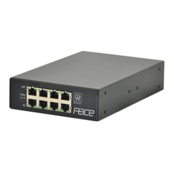
1. Pace4/8/16PRM installation:
a. Pace4PRM - Affix rubber pads to Pace4PRM for shelf installation (Fig. 5, pg. 6) .
Pace8/16PRM - Attach mounting brackets to Pace8/16PRM unit for rack installation (Fig. 4, pg. 6) .
Affix rubber pads to Pace8/16PRM for shelf installation (Fig. 5, pg. 6) .
Unit should be located in proximity to ethernet switch/network, NVR or video server.
b. Connect structured cables from port marked [IN] on Pace4/8/16PRM to the corresponding inputs of an
ethernet midspan or endspan device (Fig. 3, pg. 4) .
c. Connect structured cables from port marked [OUT] on Pace4/8/16PRM to Pace1PTM (Fig. 3, pg. 4) .
2. Pace1PTM/Pace1ST installation:
a. Secure unit to desired mounting surface with a proper fastening device utilizing the case's mounting hole.
Unit should be mounted in proximity of camera/device.
b. Connect structured cable from IP camera/device to RJ45 jack marked [PoE Out] (Fig. 2, pg. 3) .
c. Connect structured cables from Pace4/8/16PRM to RJ45 jack marked [RJ45 Link] (Fig. 2, pg. 3) .
Note: The Pace4/8/16PRM is designed to accommodate Megapixel, HD720, HD1080, and VGA (SD) cameras.
It is important to note that some high resolution and high frame rate cameras may demand faster headend
processing ability, such as a PC graphics card, to present a quality image. If the headend processing equipment
is insufficient in speed, the image may show pixelation and latency. It is advisable to pretest system if unsure.
Alternatively, frame rate and resolution may be reduced to accommodate system equipment.
Fig. 1
CAT5 Cable to Pace1PTM
OUT
Ports
1
4
IN
Structured Cable from midspan/endspan
–––––––––––––––––––––––––––––––––––––––––––––––––––––––––––––––––
Fig. 1a
CAT5 Cable to Pace1PTM
OUT
Ports
1
4
IN
Structured Cable from midspan/endspan
–––––––––––––––––––––––––––––––––––––––––––––––––––––––––––––––––
Fig. 2
N/A
CAT5 or higher
out to Pace4/8/16PRM
Pace4/8/16PRM Installation Guide
OUT
Ports
5
8
IN
OUT
Ports
5
8
IN
Pace1PTM
Green LED
indicates
PoE received
from Pace4/8/16PRM
Pace8PRM
Pace16PRM
OUT
Ports
9
12
IN
Green LED
indicates
PoE transmitted
to Camera/Device
Structured Cable
from Camera/Device
OUT
Ports
13
16
IN
Pace1ST
Pace
PoE
Receiver
Out
CAT5e or higher
Cable out to
Green LED
Pace4/8/16PRM
indicates
PoE out
to Device
IP Device
CAT5e or higher
Cable from
Camera/Device
- 3 -