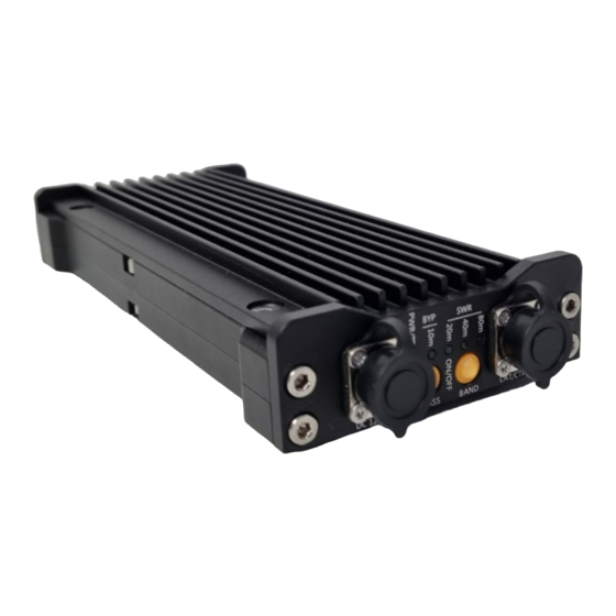
DL4KA DIY599.com PA500 Manual de instrucciones - Página 7
Navegue en línea o descargue pdf Manual de instrucciones para Sintonizador DL4KA DIY599.com PA500. DL4KA DIY599.com PA500 16 páginas. Rf linear power amplifier with build-in antenna tuner

manual band selection
The PA500 has 4 Band selector settings 80m, 40m, 20m and 10m. Most of other Frequencies
between these Bands can also be used. The table describes the selection that must be made for a
specific Band to use.
operating Band
80m
40m
20m
17m
15m
12m
10m
Only HAM frequencies are supported, Frequencies between 26-28MHz are not amplified
SWR/PWR indication
During transmit the RED, YELLOW and the green LED will show the SWR which is achieved by the
Tuner. This setting is pre-selected. Alternatively, the RF output power can also be displayed.
To toggle between both operation modes, TAP and HOLD the BYPASS Button.
SWR indication:
RED LED indicates a SWR > 2.5
YELLOW LED indicates a SWR 1.5 - 2.5
GREEN LED indicates a SWR < 1.5
compatible transceivers
Transceiver model
all devices
All transceivers
with PTT out Signal
all devices
automatic Band selection
*
all devices
automatic Band selection
automatic RF-VOX PTT
all devices
automatic Band selection
*
Default setting
Band selector setting on the
PA500
80m
40m
20m
10m
10m
10m
10m
RF Power indication:
NO LIGHT indicates RF Power < 10W
GREEN LED indicates RF Power >= 10W
YELLOW LED indicates RF Power >= 25W
RED LED indicates RF Power > 40W
Interface type
Manual mode
automatic Mode
PCB Version 2.7 and
above
*
automatic Mode
PCB Version 2.7 and
above
*
automatic Mode
PCB Version 2.4 -V2.6
7
Band selector LED Color
Interface#
PA configuration pattern
0
1
*
2
7
RED
YELLOW
GREEN
GREEN
GREEN
BLUE
BLUE
**
