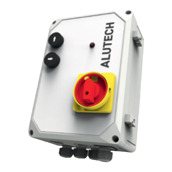
Alutech CUL11 Manual de conexión y funcionamiento - Página 8
Navegue en línea o descargue pdf Manual de conexión y funcionamiento para Unidad de control Alutech CUL11. Alutech CUL11 20 páginas.

ELECTRIC MODULE
Element
Element
hL6
hL7
J1
J2
J6
J3
J4
J5
J8
J9
J10
J12
J13
Y
ATTENTION! The position of the jumper set in J12 and J13 connectors is saved when the
on-off switch 1 (fig. 1) is switched from '0' position ('Off' position) to 'I' position ('On' position)
and maintained during the control unit operation. If the jumper position in J12 and J13
connectors is required to be changed, power off the unit, set the jumper in the appropriate
position and power on the unit.
6
6
LED indicating the operation of valve connected to VAL2 output. Lights up when the
valve is not connected to VAL2 output or voltage is supplied to the valve
LED always lights up, VAL3 output is not used for CUL11 unit
Connector for power supply connection (fig. 3)
Connectors for on-off switch 1 connection (fig. 1, fig. 3).
CAUTION! The switch is designed to turn on and turn off the voltage supplied
to the unit. Do not turn off during operation, wait until the end of the
leveller finishes its working cycle
Connector for protective earthing (PE) connection
Connector for light lamp connection 230 V / max. 100 W (fig. 4).
The lamp lights when the unit has performed any first action (control button is
pressed, door position sensor is activated) and goes out when the power is turned
off. If faults in the platform operation are detected, the lamp no longer lights
(section 7 'Faults and recommendations on their elimination')
Connector for connection of the electric motor of hydraulic unit (fig. 5) and STOP safety
sensor (NC).
CAUTION! While opening the jumper + 24 V at J5 connector, control voltage of
24 V DC turns off and control unit does not operate. For control unit
operation, OUT + 24 V and IN + 24 V contacts should be closed (NC)
Connector for connection of hydraulic unit valves (fig. 6) and door position sensor (fig. 8).
If the sensor is triggered, the electric motor of hydraulic unit turns off and the dock
leveller starts lowering
Connector for connection of the jumper to select an output type of door position sensor:
PNP or NPN (terminal output)
Connector for connection of control buttons 2 and 3, LED 4 (fig. 1, fig. 7)
The jumper for setting the overcurrent protection in the electric motor of hydraulic
unit. In the case of overcurrent or fault ( section 7 'Faults and recommendations on their
elimination'), the dock leveller movement completely stops (STOP).
CAUTION! If the jumper is not set, the protection will be turned off
Connector for connection of the jumper to select a contact type of door position sensor:
NO (normally open) or NC (normally closed).
CAUTION! If the door position sensor is not connected, the jumper should be
connected to NO contact
Description
Description
INSTALLATION AND OPERATION MANUAL | CUL11 CONTROL UNIT
