CVS Controls 667 Manual de instrucciones - Página 2
Navegue en línea o descargue pdf Manual de instrucciones para Controlador CVS Controls 667. CVS Controls 667 8 páginas. Diaphragm actuator
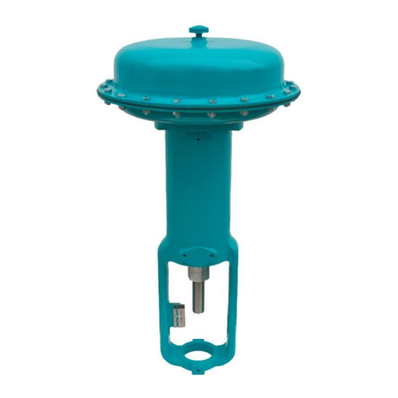
Table 1: CVS Type 667 Diaphragm Actuator Specifications
Specification
Nominal Effective Area
Yoke Boss Size Diameter
Valve Stem Size
Max. Allowable Output
Thrust
Standard
Maximum
2
Travel
Top-Loaded
Max. Diaphragm Pressure to
Stroke Actuator
Max. Excess Diaphragm
Pressure
Max. Diaphragm Case
1
Pressure
Approximate Weight
1.
Maximum diaphragm casing pressure must not be exceeded, and must not produce a force on the actuator stem greater than the maximum allowable actuator output thrust
or the maximum allowable valve stem load.
2.
Actuator travel may be less than the value specified after being connected to the valve.
Installation
The CVS Type 667 Diaphragm Actuator is usually
delivered mounted on a CVS Controls valve body.
When installing the valve body into the pipeline,
consult the instructions for that particular valve body.
Should you have any questions during the
installation procedure, consult your CVS Controls
representative.
Actuator Mounting
1. Install the stem locknuts onto the valve stem and
place the travel indicator disc onto the locknuts.
2. If the valve is direct-acting, push the valve stem
down to close the valve. If the valve is reverse-
acting, push the valve stem down to open the
valve.
3. Place the actuator onto the valve bonnet. If
necessary, use a hoist or lift the actuator in order
to slip the yoke locknut over the valve stem.
4. Screw the yoke locknut onto the bonnet securing
the actuator to the bonnet.
5. Apply required supply pressure to actuator. If
using a 6-30 signal, apply 35 psi. If using a 3-15
signal, apply 20 psi to move the actuator stem to
the top of the travel.
6. Align the indicator disc with the travel side on the
actuator by adjusting the locknuts.
7. Raise the valve plug until the travel disc aligns
with the top of the scale (full travel).
8. Clamp the actuator and valve body stems
between the two stem connector halves. Insert
and tighten both stem connector cap screws.
2
30
34
Sq. In.
46
69
Sq. cm
297
445
In.
2-1/8
2-1/8
mm
54
54
In.
3/8
3/8
mm
9.5
9.5
Lbs
2300
2300
N
10,230
10,230
In.
3/4
3/4
mm
19
19
In.
---
3/4
mm
---
19
Psig
40
45
Bar
2.8
3.1
Psig
70
45
Bar
4.8
3.1
Psig
110
90
Bar
7.6
6.2
Lb
40
60
Kg
18
27
Actuator Size
40
45
46
69
105
156
445
677
1006
2-13/16
2-13/16
2-13/16
71
71
71
1/2
1/2
1/2
12.7
12.7
12.7
2700
5650
7550
12,010
25,131
33,582
1-1/2
2
2
38
51
51
---
3/4
---
---
19
---
45
50
45
3.1
3.4
3.1
45
30
15
3.1
2.1
1.0
90
65
55
6.2
4.5
3.8
56
95
125
25
43
57
Note: Avoid clamping the tip of either the valve
stem or the actuator stem in the stem connector.
Failure to completely clamp the stems may strip
the threads and affect proper operation. The
length of each stem clamped in the stem
connector should be equal to or greater than the
diameter of that stem.
9. Lift the travel indicator disc to the stem connector
and thread the stem locknuts against the stem
connector.
10. Realign the travel indicator scale to show the
valve position.
Loading Connection
1. The loading pressure is connected to the 1/4-
inch NPT connection in the side of the yoke.
2. For the CVS 667 Actuator Size 70, remove the
1/4-inch bushing in the 1/2-inch NPT female
connection to increase the connection size if
desired. Piping or tubing can be used, but should
be kept as short as possible to avoid
transmission lag in the control signal. If an
accessory is attached to the actuator ensure that
it has been properly secured.
3. If the valve positioner is provided as part of the
original equipment, the loading pressure
connection will be made at the CVS Controls
manufacturing facility.
4. Check the valve stem travel by cycling the
actuator several times. Ensure that the proper
travel occurs when the correct pressure range is
applied to the diaphragm.
50
60
70
105
156
220
677
1006
1419
3-9/16
3-9/16
3-9/16
90
90
90
3/4
3/4
3/4
19.1
19.1
19.1
5650
6800
8800
25,131
30,246
39,142
2
2
3
51
51
76
---
1-1/8
---
---
29
---
50
45
40
3.4
3.1
2.8
30
15
15
2.1
1.0
1.0
65
55
55
4.5
3.8
3.8
97
125
254
44
57
115